
Catalog excerpts

Hydrodynamic Couplings Principles | Features | Benefits
Open the catalog to page 1
Hydrodynamic Soft-start Couplings Voith Turbo provides fluid coupling and drive solutions for the efficient and reliable operation of systems in the mining industry and the handling of raw materials. The hydrodynamic principle of a fluid coupling makes it possible to gently accelerate driven machines and to transfer power in a wear-free manner. At the same time, the fluid coupling protects the drive system to the maximum degree, even under extreme operating conditions, against damage and this reduces downtimes. Voith Turbo, a Group Division of Voith GmbH, is a specialist for intelligent...
Open the catalog to page 2
Dawn of the hydrodynamic power transmission 2.1 The operating principles of hydrodynamic 7 power transmission 3.2 Similarity laws for hydrodynamic power 12 3.2.2 Similarity of flow velocities 13 3.2.3 Similarity of hydrodynamic power transmitters 14 3.3 Interaction of several flow machines 16 3.3.1 Primary characteristic curves 17 3.3.2 Secondary characteristic curves 17 3.4 Determining characteristic curves 20 Hydrodynamic couplings Characteristic curves Fluid couplings in drive systems Electric motor, multi-motor drives Diesel engine Dependence on rotation direction and direction 30...
Open the catalog to page 3
Fig. 1: Prof. Hermann Föttinger (b. February 9, 1877 in Nuremberg [DE]; d. April 28, 1945 in Berlin [DE]) 1 Dawn of the Hydrodynamic Power Transmission The development of hydrodynamic power transmission goes back to a basic patent filed by young electrical engineer Dr. Hermann Föttinger in the year 1905. As an employee of a shipyard (Stettiner Vulkan), it was his task to combine the quickly running steam turbine (drive machine) emerging in the ship- building industry with the slow running ship’s propeller (driven machine). The steam turbine provided significantly improved efficiency...
Open the catalog to page 4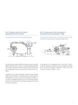
Fig. 2: Föttinger’s sketch of the idea of hydrodynamic power conversion Fig. 3: A cross-section of the drive system for the trial ship he built (constructed in 1909) The pump and turbine are still physically separate. From right to left: Steam turbine, converter for reverse travel, converter for forward travel, outgoing propeller shaft. Another idea was indirect electrical conversion using a rotating differential transformer. However, the high-voltage equipment that would be required for this on-board and the large mass and considerable volume meant that this solution was not an option. In...
Open the catalog to page 5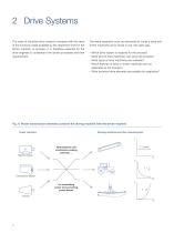
2 Drive Systems The value of industrial drive systems increases with the value of the functions made available by the respective drive for the driven machine or process. It is therefore essential for the drive engineer to understand the driven processes and their requirements. The same questions must be answered for today’s drive and driven machinery as for those in use 100 years ago: • • • • Which drive system is required for the process? What kind of drive machinery can serve the process? What types of drive machinery are available? Which features of drive or driven machinery are not...
Open the catalog to page 6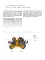
2.1 The Operating Principles of Hydrodynamic Power Transmission Transmitting power from the driver to the driven machine occurs predominantly according to the direct operating principle in conventional machine construction, for example through shafts, mechanical couplings or gear units. Despite the great variety of gear units used to convert the torque and speed through gears, belt pulleys etc., their operating mechanisms all lead back to the lever or wedge. Another advantage of the indirect torque transmission principle is the difference in transfer behavior between steady state and...
Open the catalog to page 7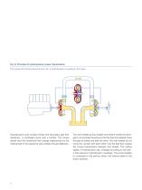
Fig. 6: Principle of hydrodynamic power transmission The pump and turbine become one unit, a hydrodynamic coupling in this case . Hydrodynamic units contain primary and secondary-part flow machinery: a centrifugal pump and a turbine. The torque results from the directional flow change experienced by the rotating fluid in the respective vane wheels through deflection. The vane wheels (pump impeller and turbine wheel) are arranged in an enclosed housing so that the fluid immediately flows through all wheels one after the other. The vane wheels do not come into contact with each other; only...
Open the catalog to page 8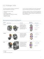
2.2 Föttinger Units The method proposed by Föttinger for hydrodynamic power transmission led to three units: • In honor of Hermann Föttinger as their inventor, hydrodynamic power transmitters are also referred to as “Föttinger Units.” Hydrodynamic torque converter (converter) Hydrodynamic coupling (turbo coupling, flow coupling, fluid coupling) Hydrodynamic brake (retarder, flow brake) The torque converter is the basic unit, with the coupling and brake being special cases. Directive VDI 2153 establishes the terms, designations, versions, principles of operation and calculation methods used....
Open the catalog to page 9
3 Hydrodynamic Principles 3.1 Fluidic Connections Processes in hydrodynamic machines and installations can be described using the relationships of fluidics. The most important physical parameters are the speed, pressure, density and viscosity of flowing media. The media can be fluid or gaseous. Hydrodynamic power transmitters actually only use fluids, since only they offer a sufficiently high density. Daniel Bernoulli and Leonhard Euler laid the foundations of fluidics in the 18th century. Building on Bernoulli’s energy equation p __ g · h + __ + 1 · c2 = Y = const. ρ 2 Euler developed...
Open the catalog to page 10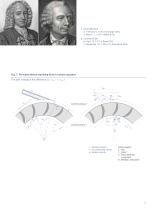
(b. February 8, 1700 in Groningen [NL] d. March 17, 1782 in Basel [CH]) 2 Leonhard Euler 1 (b. April 15, 1707 in Basel [CH] d. September 18, 1783 in St. Petersburg [RU]) Fig. 7: Principle sketch clarifying Euler’s turbine equation The spin change is the difference ( r2 · cu2 – r1 · cu1 ) c: Absolute velocity u: Circumferential velocity w: Relative velocity Indices legend: 2: Inlet 1: Outlet u: Circumferential component m: Meridian component
Open the catalog to page 11All Voith Turbo catalogs and brochures
-
Voith Schneider Propeller
12 Pages
-
Voith Linear Jet
5 Pages
-
Fast and Safe Operation
6 Pages
Archived catalogs
-
brochure marine
10 Pages


