- Catalogs
- Victron Energy
- Lynx Shunt VE.Can
Lynx Shunt VE.Can
1 /32Pages

Lynx Shunt VE.Can
1 /32Pages
Catalog excerpts

victron energy ENGLISH Lynx Shunt VE.Can Rev 01 05/2021
Open the catalog to page 1
Lynx Shunt VE.Can
Open the catalog to page 2
Lynx Shunt VE.Can
Open the catalog to page 3
Lynx Shunt VE.Can 1. Safety Precautions 1.1. Safety Warnings Lynx Distribution System • Do not work on live busbars. Ensure that the busbar is unpowered by disconnecting all positive battery poles prior to removing the Lynx front cover. • Work on batteries should be carried out by qualified personnel only. Observe the battery safety warnings as listed in the battery manual. 1.2. Transport and Storage Store this product in a dry environment. The storage temperature should be: -40°C to +65°C. No liability can be accepted for damage in transit if the equipment is not transported in its original...
Open the catalog to page 4
Lynx Shunt VE.Can 2. Introduction 2.1. The Lynx Shunt VE.Can The Lynx Shunt VE.Can contains a positive and negative busbar, a battery monitor and a fuse holder for the main system fuse. It is part of the Lynx Distribution system. The Lynx Distributor has a power LED. The Lynx Shunt VE.Can can communicate via VE.Can with an GX device. The Lynx Shunt VE.Can - with and without cover The Lynx Shunt VE.Can ships with two RJ45 VE.Can terminators, these are used when connecting to a GX device. Two RJ45 VE.Can terminators The Lynx Shunt VE.Can is designed to hold a CNN fuse. The fuse needs to be purchased...
Open the catalog to page 5
Lynx Shunt VE.Can GX devices: CCGX, Cerbo GX & GX Touch, Venus GX and Octo GX 2.3. Temperature sensor A temperature sensor can be connected to the Lynx Shunt VE.Can. It is used to measure the battery temperature. The temperature sensor is an optional extra. It needs to be purchased separately. For more information see the Temperature sensor QUA PMP GX device product page. The temperature sensor QUA PMP GX device 2.4. VictronConnect App For more information see the VictronConnect App download page and the VictronConnect manual. 2.5. The Lynx Distribution System The Lynx Distribution System is...
Open the catalog to page 6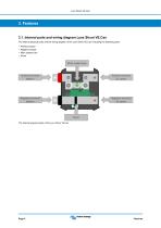
Lynx Shunt VE.Can 3.1. Internal parts and wiring diagram Lynx Shunt VE.Can The internal physical parts and the wiring diagram of the Lynx Shunt VE.Can indicating the following parts: • • • • Positive busbar Negative busbar Main system fuse Shunt Main system fuse Positive terminal Battery Positive terminal DC sytem Negative terminal Battery Negative terminal DC sytem Shunt The Internal physical parts of the Lynx Shunt VE.can
Open the catalog to page 7
Lynx Shunt VE.Can Battery monitor The internal wiring diagram of the Lynx Shunt VE.Can 3.2. Main fuse The Lynx Shunt houses the main system fuse. The fuse is being monitored by the Lynx Shunt VE.Can and, if the fuse blows, the power LED turns red and an alarm message is sent to the GX device. The relay can be driven by the blown fuse parameter. 3.3. Battery Monitor (shunt) The Lynx Shunt VE.Can battery monitor operates in a similar fashion as the other Victron Energy battery monitors. It contains a shunt and battery monitor electronics. Readout of the battery monitor data is via a GX device or...
Open the catalog to page 8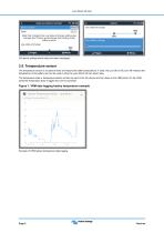
Lynx Shunt VE.Can GX device settings alarm relay and alarm messages 3.5. Temperature sensor The temperature sensor is an optional extra to measure the battery temperature. If used, the Lynx Shunt VE.Can will measure the temperature of the battery and can be used to drive the Lynx Shunt VE.Can alarm relay. The temperature data or temperature alarms will also be sent to the GX device and from there to the VRM portal. On the VRM portal the temperature data is logged and can be accessed. Figure 1. VRM data logging battery temperature example Example of VRM battery temperature data logging
Open the catalog to page 9
Lynx Shunt VE.Can 4.1. GX Device The Lynx Smart BMS can be connected to a GX device via VE.Can. The GX device will show all measured parameters, operational state, battery SoC and alarms. 4.2. NMEA2000 Communication with a NMEA2000 network can be established via the Lynx Shunt VE.Can VE.Can connection together with a VE.Can to NMEA2000 micro-C male cable. Supported NMEA 2000 PGNs: Product Information - PGN 126996 DC detailed Status - PGN 127506 DC/Battery Status - PGN 127508 Switch Bank Status - PGN 127501 - Status 1: Relay - Status 3: Battery voltage low - Status 4: Battery voltage high Class...
Open the catalog to page 10
Lynx Shunt VE.Can 5. System Design 5.1. Lynx distribution system parts A Lynx distribution system consists of a single Lynx Shunt VE.Can module. Then, single, multiple or a combination of Lynx Distributor modules and/or Lynx Power In modules are added. Together they form a continuous negative and positive busbar with DC connections and, depending on the configuration, integrated fuses, a battery monitor and/or lithium battery management. 5.1.1. Interconnecting Lynx modules Each Lynx module can connect to other Lynx modules on the left side (M8 hole) and on the right side (M8 bolt). If the Lynx...
Open the catalog to page 11
Lynx Shunt VE.Can From battery bank To DC system, All DC loads and DC charge sources Example of Lynx module orientation: the batteries connect to the left side and all loads and chargers connect on the right side The Lynx modules can be mounted in any orientation. Should they be mounted upside down, so that the text on the front of the units is upside down as well, use the special stickers are included with each Lynx module, so that the text is orientated the correct way. To DC system, All DC loads and DC charge sources From battery bank Example of Lynx modules mounted upside down: the batteries...
Open the catalog to page 12
Lynx Shunt VE.Can VE.Bus VE.Can Solar charger Lynx Power In Lynx Shunt VE.Can Lynx Distributor DC loads Temp sensor System with Lynx Shunt VE.Can, lead acid batteries, a Lynx Shunt VE.Can and a Lynx Distributor 5.2. System sizing 5.2.1. Current rating Lynx modules The Lynx Distributor, Lynx Shunt VE.Can and the Lynx Power In are rated for a nominal current of 1000A, for 12, 24 or 48 System voltages. To give an idea of how much power the Lynx modules are rated at different voltages, see below table. The power rating will give you an indication how big the connected inverter/charger system can...
Open the catalog to page 13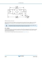
Lynx Shunt VE.Can CNN fuse dimensions in inches (mm) Always use fuses with the correct voltage and current rating. Match the fuse rating to the maximum voltages and currents that potentially can occur in the fused circuit. For more information on fuse ratings and fuse current calculations see the Wiring Unlimited book. The total value of the fuses of all circuits should not be more than the current rating of the Lynx module, or the Lynx model with the lowest current rating in case of multiple Lynx modules are used. 5.2.3. Cabling The current rating of the wires or cables used to connect the Lynx...
Open the catalog to page 14All Victron Energy catalogs and brochures
 Blue Smart IP22Charger
1 Page
 Blue Smart Charger
2 Pages
 MPPT 250/60 and MPPT 250/70
2 Pages
 BMV-712 Smart
2 Pages
 Centaur Charger
2 Pages
 Quattro Inverter/Charger120V
2 Pages
 Isolation Transformers
2 Pages
 Telecom Batteries
1 Page
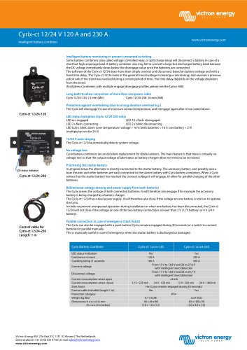 Cyrix-ct 12/24V120A and 230A
2 Pages
 Cyrix Li-ion 230A series
2 Pages
 Cyrix Li-ion 120 A series
2 Pages
 BatteryProtect
1 Page
 Phoenix Battery Charger
2 Pages
 Skylla 24/48V
2 Pages
 EasySolar 12V & 24V, 1600VA
2 Pages
 Gel and AGM Batteries
4 Pages
 Color Control GX
4 Pages
 Shore Power Cable
1 Page
 Battery Balancer
2 Pages
 Filax 2
1 Page
 2021 Marine
120 Pages
 BlueSolar PWM-Pro
1 Page
 Mobility
8 Pages
 Energy Storage
64 Pages
 EasyPlus
4 Pages
 Autotransformer 120/240V -
2 Pages
 BatteryProtect 48V-100A
1 Page
 2016 Marine
108 Pages
 Skylla-i Battery Charger 24V
2 Pages
 Quattro 3kVA - 10kVA 230V
2 Pages
 Autotransformer 32A and 100A
2 Pages
 Phoenix Inverter 3000VA - 5000VA
96 Pages
 solarswitch
8 Pages
 vgr
vgr4 Pages
 victron multipower
4 Pages
 ECOmulti
2 Pages
 Brochure marine
108 Pages
 BlueSolar MPPT 150/70
1 Page
 BlueSolar MPPT 100/15
1 Page
 BMV-700 series
2 Pages
 Skylla-i
2 Pages
 Quattro
2 Pages
 Phoenix Charger
2 Pages


Archived catalogs
 Converters
2 Pages
 Marine Alternator
6 Pages
 Phoenix Inverter
2 Pages
 Battery Monitor
2 Pages
 Centuar Charger
2 Pages
 Phoenix MultiPlus
2 Pages
- Boat indicator
- Taylor Made boat battery
- Taylor Made boat control panel
- Boat switch
- Boat charger
- Taylor Made display
- Boat cable
- Taylor Made 12 V battery
- Marine inverter
- Nautical battery switch
- Boat display
- Digital indicator
- Rigid solar panel
- Electrical circuit switch
- DC converter
- Voltage converter
- Lead battery
- 36 cells solar panel
- Boat selector