
- Catalogs
- Trelleborg Marine and Infrastructure
- Fender Application Design Manual


- Products
- Catalogs
- News & Trends
- Exhibitions
Fender Application Design Manual

Fender Application Design Manual
Trelleborg Marine and Infrastructure focuses on a 'Smarter Approach' to fender design, integrating global expertise with local insights to optimize port operations. Their fender systems are engineered for durability, low maintenance, and compliance with international standards such as PIANC 2002 and ISO17357-1:2014.
The design process includes early consultation to ensure optimal fender systems, taking into account local standards and regulations. Trelleborg's Engineering Centers of Excellence in India manage conceptual designs, providing detailed engineering analyses and CAD drawings.
All products are manufactured in-house to maintain quality control. Rigorous testing is conducted throughout the manufacturing process to meet lifecycle and performance specifications.
Installation is supported by dedicated project management, emphasizing ease of installation and future maintenance. Trelleborg offers global customer support, including training and onsite services.
Fender design considers environmental factors such as tidal ranges, currents, and winds. Different berthing locations, from sheltered basins to open waters, influence fender selection and design.
Different ship types, including cargo ships, bulk carriers, container ships, and tankers, have specific fender requirements based on their operational characteristics and berthing needs.
Trelleborg's fender systems aim to reduce construction costs, improve berth efficiency, and provide long-term value through reduced maintenance and enhanced safety.
- Bow Flares: Large flare angles on container vessels and cruise ships may require larger fenders.
- Bulbous Bows: Common in modern ships, care is needed to prevent them from getting caught behind fenders.
- Beltings & Strakes: Found on various ship classes, they require careful handling to avoid snagging.
- Flying Bridge: Common on cruise and RoRo ships, caution is needed to prevent the bridge from sitting on fenders during tide changes.
- Low Freeboard: Seen in barges and small tankers, fenders should be extended to prevent being caught underneath during low tides.
- Stern & Side Doors: Large doors on RoRo ships can snag fenders, especially in locks.
- High Freeboard: Found in ferries and cruise ships, strong winds can increase berthing speeds.
- Low Hull Pressure: Required by tankers and gas carriers, achieved using large fender panels.
- Aluminium Hulls: High-speed vessels require fender loads at specific reinforced positions.
- Special Features: Modifications can affect berthing; large bevels and chamfers can reduce risks.
- Various ship types are defined by dimensions such as length, beam, and draft, with specific classes like Panamax, Suezmax, and Seaway-Max.
- Ship tables provide detailed specifications for different vessel types, including tankers, bulk carriers, LNG carriers, and container ships.
- Dimensions and capacities vary, with notes on potential variations due to construction and origin.
- Tables list vessel types, deadweight tonnage (DWT), displacement, length overall (LOA), beam, laden draft, and capacity.
- Specific data for tankers, bulk carriers, LNG carriers, container ships, RoRo ships, cargo vessels, car carriers, ferries, and cruise liners are provided.
- Dimensions may vary up to ±10% based on construction and country of origin.
The operating capacity of a fender is determined by factors such as range, angle, impact velocity, and manufacturing tolerance. The energy capacity under worst conditions must exceed the abnormal design Berthing Energy EA.
- Strain Rate: Reaction force is proportional to strain rate. Larger fenders have lower strain rates at the same velocity, resulting in lower velocity factors (VF).
- Rubber Type: Natural rubber (NR) has a lower VF than synthetic rubber (SBR) due to different stress relaxation rates.
VF is the ratio of reaction force at impact speed to testing speed. It is influenced by strain rate and rubber type. Higher strain rates increase VF. Performance data often lacks high impact velocity considerations, which should be included in engineering designs.
TF accounts for temperature effects on fender performance. High temperatures soften fenders, reducing energy absorption, while low temperatures increase reaction forces. TF varies with rubber type.
VF affects fender performance, influencing reaction force and energy absorption. Design must consider increased forces on components and structures. Manufacturers should provide VF guidance for accurate comparisons.
Rubber type significantly impacts VF and TF. NR/SBR blends offer stable properties, while 100% NR is preferred for low temperatures and load-sensitive structures. 100% SBR suits high-speed berthing.
Tables provide VF and TF values for different rubber compositions and conditions. Angle factors adjust for angular compression effects on energy and reaction forces.
Fender chains are crucial for mooring floating fenders and preventing loss of fixed fenders during accidents. The design of these chains must consider factors like corrosion, which reduces link diameter and weakens the chain. A 'weak link' is desirable to prevent damage to more costly components. Typical friction coefficients for materials like UHMW-PE, HD-PE, and steel are provided, with UHMW-PE having the lowest friction coefficient.
UHMW-PE is highlighted as an ideal material for fender panels due to its low friction, impact strength, and resistance to wear and environmental factors. It is available in various sizes and can be customized for different applications. Key properties include density, dynamic friction, and abrasion resistance, with specific values provided for virgin and regenerated materials.
Paint coatings following ISO EN 12944-5:2007 standards are used for corrosion protection in marine environments. The document outlines different paint systems and their expected durability, emphasizing the importance of proper design to avoid corrosion traps. Galvanizing and the use of stainless steels are also discussed as methods for corrosion prevention.
The document discusses the importance of pitting resistance in stainless steels, with the PREN formula used to compare grades. Galvanizing methods, including hot dip and spin galvanizing, are explained, with typical thicknesses provided.
Testing procedures for fenders are detailed, following PIANC guidelines to ensure product quality and performance. The document outlines the test apparatus, procedures, and reporting requirements, emphasizing the importance of rigorous testing to ensure reliability and reduce lifetime costs.
Testing involves verifying the performance of fenders under controlled conditions, with specific steps outlined for the Constant Velocity (CV) test method. Reports must include detailed information about the test, including customer and project details, test conditions, and results.
- Constant velocity: 2 - 8 cm/min
- Impact speed: 0.001m/s to 0.5m/s
- Temperature range: –30°C to +50°C
- Compression angle: 0° to 20°
- Durability: Minimum 3000 cycles
- Type Approval testing should be monitored by accredited third-party inspectors.
- Verification testing is conducted to ensure fender performance, using samples from the project.
- Results are adjusted using correction factor tables for initial impact speed and temperature.
- No visual evidence of bond failure or splits.
- Reaction Force (RVT) and Energy Absorption (EVT) must meet specified conditions relative to CV Performance Data.
- Deflection is not a pass/fail criterion.
- Rubber is a visco-elastic material affected by speed of compression and temperature.
- Types of rubber include Natural Rubber, Synthetic Rubber (SBR), and EPDM.
- Recycled rubber is used for cost reduction but has lower physical properties.
- Fillers such as carbon black are used for reinforcement.
- A rubber compound consists of multiple ingredients, including polymer, filler, antioxidants, and oils.
- Superior compounds have a rubber to filler ratio greater than 1.2 and a density close to 1.
- The document outlines the proprietary nature of rubber formulations used in fender manufacturing, emphasizing the importance of ingredient ratios to achieve desired properties.
- Rubber compounding is described as a science, with modern tools making it more predictable than in the past.
- Low-quality fenders degrade faster due to environmental factors and often use lower-cost, recycled rubber with high non-reinforcing filler content.
- Key indicators for rubber quality include polymer percentage, carbon black content, specific gravity, ash content, and rubber-to-filler ratio.
- Standard specifications for these indicators are provided, with tests available to verify supplier claims.
- Infrared spectroscopy (FTIR) and thermo gravimetric analysis (TGA) are used to determine the chemical composition of rubber compounds.
- These tests help ensure the quality of fenders by analyzing polymer composition and other key parameters.
- Proper mixing of rubber compounds is crucial for maintaining the physical properties and performance of fenders.
- High-quality carbon black dispersion is essential for achieving the right modulus and ensuring long service life.
- Internal mixers are preferred over kneaders for better control of mixing parameters and achieving high dispersion ratings.
- Fenders submerged in water can experience increased reaction forces due to water pressure, potentially leading to structural failures.
- Design considerations include providing exit routes for water to minimize force increases during compression.
- The document lists various testing standards and requirements for properties such as tensile strength, elongation at break, hardness, compression set, tear strength, ozone resistance, and abrasion resistance.
- These properties are confirmed during quality assurance testing to ensure compliance with international fender recommendations.
Trelleborg fenders are designed with specific tolerances for various types, including molded, composite, keyhole, cylindrical, extruded, and sliding fenders. These tolerances cover dimensions, bolt hole spacing, and performance parameters such as reaction and energy absorption.
Fenders are tested at compression speeds of 2-8 cm/min, but real-life performance may differ due to varying berthing velocities. The Velocity Factor (VF) and Temperature Factor (TF) are used to adjust performance data to account for these differences.
The document references several standards and guidelines, including ISO 1817, ASTM D471, PIANC guidelines, and others related to the design and testing of fender systems.
Designers should consider VF and TF during the design process to ensure accurate performance predictions. The composition of rubber significantly affects VF and TF, and different manufacturers may have varying VF values.
The FAQ section addresses common concerns about fender testing, performance differences at various velocities, and the impact of rubber composition on fender longevity and performance.
A comprehensive glossary of symbols and terms used in fender design and testing is provided, covering aspects like vessel dimensions, reaction forces, and berthing velocities.
Several codes and guidelines are listed, including PIANC 2002, BS6349-4:2014, and others that provide frameworks for fender system design and testing.
Catalog excerpts

Fender Application Design Manual DESIGN MANUAL
Open the catalog to page 1
The Smarter Approach The smarter approach for a more efficient port Transferring know-how for smarter LNG Connect with The Smarter Approach By Trelleborg Marine and Infrastructure Visit: Converse: @TrelleborgMI Explore: marineandinfrastructure Discover: TrelleborgMarineandInfrastructure Materials best practice for a smarter port The demanding nature of commercial ports and terminals means you need partnership that provides much more than technically superior products and technologies. You need to work with a partner that combines best practice expertise gained through worldwide experience with...
Open the catalog to page 2
Fender Application Design Manual Trelleborg Marine and Infrastructure is a world leader in the design and manufacture of advanced marine fender systems. We provide bespoke solutions for large and complex projects all over the world. Best practice design and quality materials ensure a long, low maintenance service life, no matter how demanding the working and environmental conditions. All fenders are supplied fully tested and meet PIANC 2002 guidelines. Our pneumatic fenders are also completely ISO17357-1:2014 compliant. Our high performance solutions combine low reaction force and hull pressure...
Open the catalog to page 3
A Smarter Approach at every stage A smarter approach to... CONSULTATION Consultation from the earliest project phase to ensure the optimum fender systems and marine technology solutions are specified, with full technical support from our global offices. Conceptual design in your local office – with full knowledge of local standards and regulations, delivered in your language – for optimized port and vessel solutions. Concepts are taken to our Engineering Centers of Excellence in India where our team generates 3D CAD designs, applicationengineering drawings, a bill of materials, finite engineering...
Open the catalog to page 4
Across our entire product range, stringent testing comes as standard at every step in our in-house manufacturing process. We ensure that lifecycle and performance of our entire product range meets your specifications, and more. Dedicated project management, from solution design right the way through to on-site installation support. We design products and solutions that always consider ease of installation and future maintenance requirements. Local support on a truly global scale, with customer support teams all over the world. And this service doesn’t stop after a product is installed. You have...
Open the catalog to page 5
As stated in the British Standard*, fender design should be entrusted to ‘appropriately qualified and experienced people’. Fender engineering requires an understanding of many areas: Fender systems should be self-protective and reliably protect ships and structures. They should be long-lasting, requiring minimum maintenance, to withstand the harsh environment in which they operate. ❙ Civil construction methods ❙ Regulations and codes of practice * BS6349 : – Code of Practice for Design of Fendering and
Open the catalog to page 6
USING THIS GUIDE This guide addresses many of the frequently asked questions which arise during fender design. All methods described are based on the latest recommendations of PIANC as well as other internationally recognized codes of practice. These guidelines do not encompass unusual ships, extreme berthing conditions and other extreme cases for which specialist advice should be sought. Methods are also adapted to working practices within Trelleborg and to suit Trelleborg products. Further design tools and utilities including generic specifications, energy calculation spreadsheets, fender performance...
Open the catalog to page 7
Why Fender? ‘There is a simple reason to use fenders: it is just too expensive not to do so’. These are the opening remarks of PIANC and remain the primary reason why every modern port invests in protecting their structures with fender systems. Well-designed fender systems will reduce construction costs and will contribute to making the berth more efficient by improving turn-around times. It follows that the longer a fender system lasts and the less maintenance it needs, the better the investment. It is rare for the very cheapest fenders to offer the lowest long term cost. Quite the opposite...
Open the catalog to page 8
Design Flowchart Functional type(s) of cargo safe berthing and mooring better stability on berth reduction of reaction force Operational berthing procedures frequency of berthing limits of mooring and operations (adverse weather) range of vessel sizes, types special features of vessels (flare, beltings, list, etc) allowable hull pressures light, laden or partly laden ships stand-off from face of structure (crane reach) fender spacing type and orientation of waterfront structure special requirements spares availability Site conditions wind speed wave height current speed topography tidal range...
Open the catalog to page 9
The Design Process Many factors contribute to the design of a fender system: SHIPS Ship design evolves constantly – changes in shapes and increasing vessel sizes. Fender systems must suit current ships and those expected to arrive in the foreseeable future. STRUCTURES Fenders impose loads on the berthing structure. Many berths are being built in exposed locations, where fender systems can play a crucial role in the overall cost of construction. Local practice, materials and conditions may influence the choice of fender systems. APPROACH Many factors will affect how vessels approach the berth,...
Open the catalog to page 10
Berthing Environment & Energy calculation As well as a full suite of engineering programs, we have expert designers who are experienced in all industry relevant CAD programs. We have a dedicated team who will provide a tailored solution for your project, on time and on budget.
Open the catalog to page 12
Environment TYPICAL BERTHING LOCATIONS Berthing structures are located in a variety of places from sheltered basins to unprotected, open waters. Local conditions will play a large part in deciding the berthing speeds and approach angles, in turn affecting the type and size of suitable fenders. Non-tidal basins Tidal basins With minor changes in water level, these locations are usually sheltered from strong winds, waves and currents. Ship sizes may be restricted due to lock access. Larger variations in water level (depends on location) but still generally sheltered from winds, waves and currents....
Open the catalog to page 13All Trelleborg Marine and Infrastructure catalogs and brochures
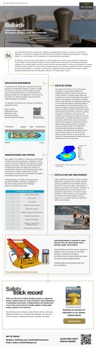 Bollard infographic
1 Page
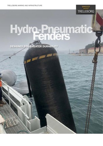 Hydro-Pneumatic Fenders (HPNE)
10 Pages
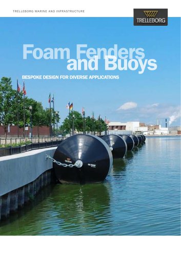 Foam Fenders & Buoys
24 Pages
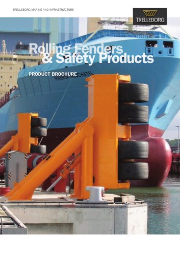
Archived catalogs
 SafePilot brochure
20 Pages
 Fender Systems
86 Pages
 AutoMoor Brochure
24 Pages
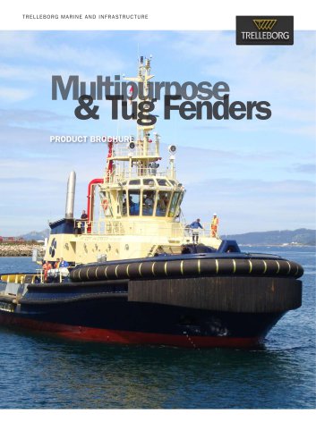
 Multipurpose and Tug Fenders
44 Pages
 Solid SmartFender Factsheet
2 Pages
 Bollards
28 Pages
 Pneumatic Fenders brochure
28 Pages
 DynaMoor
20 Pages
 Rolling Fenders and Safety
18 Pages
 Ship-Shore Links Factsheet
4 Pages
 TRELLEBORG’S Tugger Winch
2 Pages
 Universal Safety Link
3 Pages
 Docking & Mooring
88 Pages
 Performance Monitoring
3 Pages
 SmartDock ® Display Board
4 Pages
 LNG Infographic
8 Pages
 SmartMoor Series II
7 Pages
 Surface Buoyancy
24 Pages
 TRELLEBORG DYNAMOOR
4 Pages
 Accessories
10 Pages
 SmartDAS Factsheet
2 Pages
 Capstans
4 Pages
 Remote Release System
6 Pages
 lload monitoring software
2 Pages
 Barometer Report 2
7 Pages
 lload monitoring systeme
5 Pages
 Guide - Fenders
8 Pages
 Mini Guide - Foam Fenders
5 Pages
 Barometer Report 3
16 Pages
 Hawser Hooks
6 Pages
 Whitepaper - Correction Factors
10 Pages
 Buoy Range Table
2 Pages
 SafePilot CAT XT System
2 Pages
 AutoMoor Datasheet
4 Pages
 Ship Shore Link System
3 Pages
 Combined ESDS & SSL
3 Pages
 Prelude LNG
1 Page
 Floating Fenders
48 Pages
 Emergency Shutdown Link
3 Pages
 Safepilot SmartPort System
16 Pages
 SafePilot User Guide
30 Pages
 Docking and mooring
2 Pages


- Nautical buoy
- Ship winch
- Motorboat fender
- Dock fender
- Plastic buoy
- Floating boom
- Cylindrical fender
- Black fender
- Hydraulic drive winch
- Trelleborg harbor fender
- Containment boom
- Inflatable fender
- Trelleborg pier fender
- Manual ladder
- Nautical mooring buoy
- Nautical capstan
- Polyethylene buoy
- Sheltered waters boom
- Anchor chain