
- Catalogs
- Transfluid
- K - CK - CCK FLUID COUPLINGS

K - CK - CCK FLUID COUPLINGS
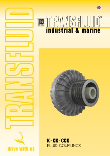
K - CK - CCK FLUID COUPLINGS
The TRANSFLUID coupling (K series) is a constant fill fluid coupling that functions as a hydrodynamic transmission. It consists of a driving impeller, a driven impeller, and a cover with an oil-tight seal. The coupling transfers kinetic energy from the input drive to the oil, which then transmits torque to the output shaft. Efficiency is influenced by the slip between the pump and turbine, which is crucial for torque transmission.
Fluid couplings help reduce the motor's current peak during start-up, extending the motor's lifespan. They allow more torque to be transferred to the load for acceleration compared to direct drive systems, resulting in smoother acceleration and reduced current absorption during start-up.
Fluid couplings with delayed fill chambers can limit starting torque to less than 200% of the nominal motor torque. This feature is advantageous for machinery with large inertia values, providing smooth start-ups and reducing current absorption.
Fluid couplings offer smooth start-ups, protect motors from overloads, and allow the use of standard motors instead of special ones. They also absorb torsional vibrations and enable frequent start-ups and direction reversals.
Standard mounting involves the driver inner impeller, while reverse mounting involves the driver outer impeller. Each configuration has specific advantages and considerations, such as ease of maintenance and heat dissipation capacity.
The document outlines various versions of fluid couplings, including in-line and pulley versions, each designed for specific applications and configurations.
ATEX-certified fluid couplings are available for use in hazardous zones, requiring an additional safety factor in their selection.
The document provides guidelines for selecting the appropriate fluid coupling based on power requirements and includes detailed dimensions for different versions.
Transfluid offers additional safety devices and a range of other products to complement their fluid couplings.
Special bearings and seal fluid are required for operations below -20°C. Water used should be a mixture of water and glycol. Water fill couplings are available from size 13 upwards and are identified with a suffix 'W'.
Fluid couplings are categorized based on their explosion protection levels and temperature ratings. Categories range from 1 to 3, with specific models like KRG, KCG, KDM, etc., having different certifications for gas and dust environments.
The selection of fluid couplings is based on horsepower and input speed. A selection chart and table are provided to assist in choosing the appropriate unit size. It is recommended to select a larger size if the selection point falls on a size limit line.
For frequent starts or high inertia acceleration, calculations are necessary to determine acceleration time, maximum allowable temperature, and maximum working cycles per hour. The final coupling temperature should not exceed 150°C.
Dimensions for various series (KRG, KRB, KRBP, etc.) are provided, with specifications for brake drums and discs. Installation instructions include details on bore dimensions and keyway standards.
Dimensions are subject to change without notice. Special instructions are provided for installations on shafts without shoulders and for ordering specific models and sizes.
The document provides technical specifications and operational guidelines for various safety and control devices used in fluid couplings. It includes details on installation, operation, and maintenance of these devices, as well as additional product offerings from Transfluid.
- Percussion Fusible Plug: Designed to operate an alarm or motor trip signal. It can be restored by replacing the percussion plug or fusible ring. Suitable for installation on all fluid couplings from size 13K.
- Standard Fusible Plug: Installed to increase safety, set at a higher temperature than the percussion fusible plug.
- Measures speed variation between input and output of the fluid coupling.
- Triggers an alarm or stops the motor if the set threshold is exceeded.
- Includes a timer to prevent false alarms during startup and sudden torque changes.
- Available in standard and Atex versions, with various power supply options.
- Non-contact system for measuring fluid coupling temperature.
- Equipped with adjustable alarm thresholds and requires painting the coupling surface black for accurate readings.
- Standard sensor cable length is 90 cm, extendable with specific wiring.
- Includes settings for speed range, set point, and delay time.
- Features manual and remote reset options, with LED indicators for status and alarms.
- Fluid Couplings (KSL and KPT Series), Flexible Couplings (BM-B3M Series), Pneumatic Clutches (TP Series), Disc & Drum Brakes (NBG/TFDS Series), and Electric Machines.
Details for Transfluid's offices in Italy, China, France, The Netherlands, Germany, USA, and the UK are provided for further inquiries.
Catalog excerpts
FLUID COUPLINGS
Open the catalog to page 1
STARTING TORQUE CHARACTERISTICS 4 STANDARD OR REVERSE MOUNTING 6 SPECIAL VERSION (ATEX) 8 DIMENSIONS (IN LINE VERSION) 13 - 23 CENTER OF GRAVITY AND MOMENT OF INERTIA 24 DIMENSIONS (PULLEY VERSIONS) 25 - 26 OTHER TRANSFLUID PRODUCTS 30 SALES NETWORK
Open the catalog to page 2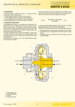
DESCRIPTION & OPERATING CONDITIONS industrial & marine Slip % = 1. DESCRIPTION The TRANSFLUID coupling (K series) is a constant fill type; comprising of three main elements: 1 - driving impeller (pump) mounted on the input shaft. 2 - driven impeller (turbine) mounted on the output shaft. 3 - cover, flanged to the outer impeller, with an oil-tight seal. The first two elements can work both as pump or turbine. The TRANSFLUID coupling is a hydrodynamic transmission. The impellers perform asva centrifugal pump and a hydraulic turbine. With an input drive to the pump (e.g. electric motor or Diesel...
Open the catalog to page 3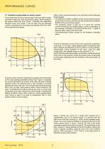
PERFORMANCE CURVES 2.1 Transfluid coupling fitted on electric motors With a motor connected directly to the load there are the following disadvantages: • The difference between available torque and the torque required by the load is very low until the rotor has accelerated to between 80-85% of the synchronous speed. • The absorbed current is high (up to 6 times the nominal current) throughout the starting phase causing overheating of the windings, overloads in the electrical lines and, in cases of frequent starts, major production costs. • Over-dimensioned motors caused by the limitations indicated...
Open the catalog to page 4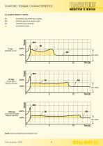
STARTING TORQUE CHARACTERISTICS 2.2 CHARACTERISTIC CURVES : transmitted torque from fluid coupling : starting torque of the electric motor : nominal torque at full load : accelerating torque K type (standard circuit) CK type (circuit with a delayed chamber) CCK type (circuit with a double delayed chamber) NOTE: Above starting times are indicative only
Open the catalog to page 5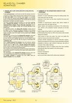
DELAYED FILL CHAMBER ADVANTAGES 3. TRANSFLUID FLUID COUPLINGS WITH A DELAYED FILL CHAMBER 3.1 SUMMARY OF THE ADVANTAGES GIVEN BY FLUID COUPLINGS A low starting torque is achieved and with the standard circuit in – very smooth start-ups a maximum oil fill condition because fluid couplings limit the torque to less than 200% of the nominal motor torque. It is possible to limit further the starting torque down to 160% of the nominal torque, by decreasing oil fill: however, this creates slip and working temperature increase in the fluid coupling. The most convenient technical solution is to use fluid...
Open the catalog to page 6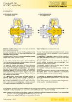
STANDARD OR REVERSE MOUNTING 4. INSTALLATION 4.1 STANDARD MOUNTING Driver inner impeller 4.2 REVERSE MOUNTING Driver outer impeller Minimum possible inertia is added to the motor, and therefore free to accelerate more quickly. Higher inertia directly connected to the motor. During the starting phase, the outer impeller gradually reaches the steady running condition. For very long starting times, heat dissipation capacity is lower. The outer impeller, being directly connected to the motor, reaches synchronous speed instantly. Ventilation is therefore maximum from the beginning. If a braking system...
Open the catalog to page 7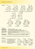
PRODUCTION PROGRAM CKRG - CCKRG CKRBP - CCKRBP CKRD - CCKRD CKCG - CCKCG CKDM - CCKDM CKDMBP - CCKDMBP 5.1 IN LINE KRG-CKRG-CCKRG KRB-CKRB-CCKRB KRD-CKRD-CCKRD KRG3-CKRG3-CCKRG3 KRM-CKRM-CCKRM EK KCG-CKCG-CCKCG KDM-CKDM-CCKDM N.B.: : coupling with elastic coupling. : KRG version, with brake drum (...KRB) or disc (...KRBP). : ...KR with output shaft. A flexible coupling has to be used; it is possible to place it (with a convenient housing) between the motor and a hollow shaft gearbox. : version with elastic coupling allowing removal of rubber elements without moving the machines. : coupling with...
Open the catalog to page 8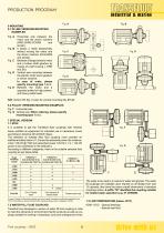
PRODUCTION PROGRAM industrial & marine 6 MOUNTING6.1 IN LINE VERSIONS MOUNTING EXAMPLES Fig. A Horizontal axis between the motor and the driven machine (KRG-CKRG-CCKRG and similar). Fig. B It allows a radial disassembly without moving the motor and the driven machine (KCG-KDM and similar). Fig. C Between a flanged electric motor and a hollow shaft gearbox by means of a bell housing (...KRD and EK). Fig. D Vertical axis mounting between the electric motor and a gearbox or driven machine. In case of order, please specify mounting type 1 or 2. Fig. E Between the motor and a upported pulley for high...
Open the catalog to page 9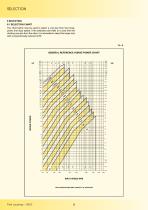
SELECTION 8 SELECTION 8.1 SELECTION CHART The chart below may be used to select a unit size from the horsepower and input speed. If the selection point falls on a size limit line dividing one size from the other, it is advisable to select the larger size with a proportionally reduced oil fill. GENERAL REFERENCE HORSE POWER CHART HORSE POWER THE CURVES SHOW LIMIT CAPACITY OF COUPLING
Open the catalog to page 10
industrial & marine 8.2 SELECTION TABLEFluid coupling for standard electric motors. Tab. B max. max. max. NB: THE FLUID COUPLING SIZE IS TIED TO THE MOTOR SHAFT DIMENSIONS
Open the catalog to page 11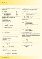
For frequent starts or high inertia acceleration, it is necessary to first carry out the following calculations. For this purpose it is necessary to know: For simplicity of calculation, ignore the heat dissipated during acceleration. Coupling temperature rise during start-up is given by: P|_ - power absorbed by the load at rated speed kW n|_ - speed of driven machine rpm J - inertia of driven machine kgm2 where: Q = heat generated during acceleration (kcal) C = total thermal capacity (metal and oil) of coupling selected from Tab. C (kcal/°C). The preliminary selection will be made from the selection...
Open the catalog to page 12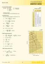
8.4 CALCULATION EXAMPLE Assuming: Pm = 20 kW nm = 1450 giri/min From selection graph. on Tab. A, selected size is 12K. A) Acceleration time From curve Tf 5078-X (supplied on request) slip S = 4% THERMAL CAPACITY C) Max working cycles per hour tL
Open the catalog to page 13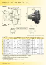
SERIES 7 ÷ 19 - KRG - KRB - KRBP - CK... - CCK... 9. DIMENSION (with brake drum) (with brake disc) CKRG - CCKRG In case of installation on shafts without shoulders, please contact Transfluid taper bush cylindrical bore DIMENSIONS ARE SUBJECT TO ALTERNATION WITHOUT NOTICE Size CKRG CCKRG brake disc CKRG CCKRG D BORES RELATIVE TO TAPER BUSHES WITH A KEYWAY ACCORDING TO ISO 773 - DIN 6885/1 PARTICULAR CASES: • CYLINDRICAL BORE WITHOUT TAPER BUSH WITH A KEYWAY ISO 773 - DIN 6885/1 •• CYLINDRICAL BORE WITHOUT TAPER BUSH, WITH A REDUCED KEYWAY (DIN 6885/2) ••• TAPER BUSH WITHOUT KEYWAY – FOR …KRB -...
Open the catalog to page 14All Transfluid catalogs and brochures
 Battery pack
4 Pages
 Electric propulsion system
28 Pages
 Hybrid Booster
4 Pages
 POWER TRANSMISSION EQUIPMENT
5 Pages
 KX
KX4 Pages
 RBD
RBD7 Pages
 B3M-BM-BMS FLEXIBLE COUPLINGS
12 Pages
 GEAR COUPLINGS P SERIES
12 Pages
 SL SPRING LOADED BRAKES
4 Pages
 SH-SHC OIL ACTUATED CLUTCHES
8 Pages
 KSL
KSL8 Pages
 KPTO
KPTO4 Pages
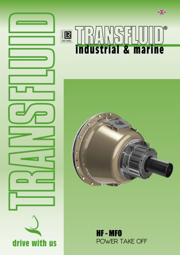 HF - MFO POWER TAKE OFF
8 Pages
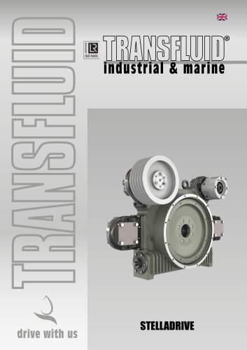 STELLADRIVE
8 Pages
 Power Shift Transmissions
8 Pages
 Marine transmissions
16 Pages
 High Speed
5 Pages




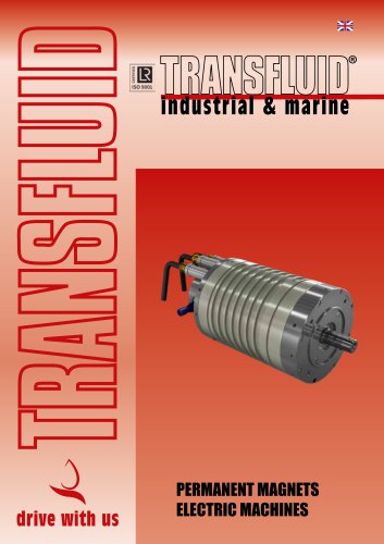

Archived catalogs
 TOWERCLUTCH
5 Pages
- Transfluid inboard engine
- Professional engine
- Outboard engine
- Transfluid electric engine
- Water-cooled engine
- Transfluid propulsion engine
- Professional vessel engine
- Boat battery
- Motor reduction gearbox
- Boat reduction gearbox
- Lithium battery
- Auxiliary engine
- Transfluid mechanical coupling
- Transmission reduction gearbox
- Transfluid boat engine
- Nautical propulsion system
- Transfluid permanent magnet engine
- Transfluid boat mechanical coupling
- Saildrive engine
- Transfluid synchronous engine