- Catalogs
- Tides Marine
- SureSeal INSTALLATION MANUAL
SureSeal INSTALLATION MANUAL

SureSeal INSTALLATION MANUAL
Tides Marine introduced the STRONG® Shaft Seal System in 1991, which includes the SureSeal Unit, Spare Seal Carrier, and Water Pick-up Kit. The system is designed to provide high-quality performance with components that are durable and easy to install.
The SureSeal unit is the core of the system, offering a housing made from a fiber-reinforced composite material that is strong and dimensionally stable. It features a PTFE bearing for extended life and an articulating hose for easy installation and reduced side loads. The hose clamps are designed to prevent damage and require less tightening force. The unit allows for easy seal replacement with a removable front cap.
The installation process involves removing the old shaft sealing system, preparing the shaft, and installing the SureSeal unit with the articulating hose. The system must be connected to a pressurized water supply for lubrication. Detailed instructions are provided with each product.
The Spare Seal Carriers provide a convenient storage for spare lip seals and facilitate easy seal replacement without uncoupling the shaft. They are available in various sizes and include spare seals.
The Water Pick-Up Kits are designed to connect the STRONG® Seal unit to a pressurized water source. They include various fittings for installation and ensure proper cooling and lubrication of the shaft seals. The kits come with detailed installation instructions.
Recommended water pick-up points include locations in the engine's raw water system, such as between the heat exchanger and riser, or between the oil cooler and heat exchanger. Proper orientation and maintenance of the pick-up points are crucial for optimal performance.
Before operating the vessel, it is essential to test the water supply system to ensure adequate water flow at idle and throughout the RPM range. For twin-engine setups, a crossover line is recommended to ensure proper lubrication when only one engine is running.
Catalog excerpts

1.0 .1 .2 TM STRONG ® SureSeal System Shaft Seals, Spare Seal Carriers & Water Pick-up Kits ® S T R O N G
Open the catalog to page 1
Tides Marine introduced its first commercial STRONG® product line improvements have made the STRONG® Shaft Seal System the industry standard. The system is comprised of three components; the SureSeal™ Unit, the Spare Seal Carrier, and the Water pick-up kit.
Open the catalog to page 2
SureSealdescription Committed to providing our customers with the highest quality products, Tides Marine for 2001 is now shipping the new style SureSealTM unit as the center of its Shaft Seal System. Developed to replace our older style UHMW STRONG® Seals, these units are guaranteed for 2500 engine hours or two years (whichever comes first) and offer several performance enhancements including: Housing- Made from a new fiber-reinforced composite material, the housing is stronger, smaller and more durable than its predecessor. Dimensionally unaffected by temperature changes, the SureSeal will not...
Open the catalog to page 3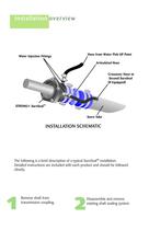
installation overview Hose from Water Pick-UP Point Water Injection Fittings Articulated Hose Crossover Hose to Second SureSeal (If Equipped) STRONG® SureSealTM Stern Tube INSTALLATION SCHEMATIC The following is a brief description of a typical SureSealTM installation. Detailed instructions are included with each product and should be followed closely. 1 Remove shaft from transmission coupling. 2 Disassemble and remove existing shaft sealing system.
Open the catalog to page 4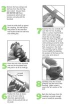
Remove the hose clamps and old hose from the shaft log (stern tube). Discard them. components which will not function correctly with the Draw the shaft back up against the coupling. This will expose that portion of the shaft that was located under the old hose Examine this area carefully. Be sure that it is free of pitting, nicks or surface imperfections which could cause leaking. Clean this area thoroughly. Polish the shaft using 300 grit wet/dry sandpaper or emery cloth working around the shaft. Fore and aft actions could put flats or grooves in the shaft. forward slightly by adjusting stern...
Open the catalog to page 5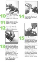
10 11 12 13 Carefully slide the assembly (hose end first) onto the shaft so that the shaft passes through the red seal protector. 14 Pull the red seal protector from the SureSeal. Separate the tabs to split the cone and remove it from the shaft. 15 Connect the STRONG® SureSealTM to a pressurized water supply source (point in the engine's raw water cooling system) by attaching the water injection hose to the stainless steel fitting on the housing. If there is a second hose fitting on the SureSeal, it is used to complete a crossover feed between the port and starboard shaft seals. Complete crossover...
Open the catalog to page 6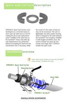
spare seal carriers STRONG® Spare Seal Carriers were developed as a convenient place to store spare lip seals and as a tool for making the job of seal replacement easier. Installed at the same time as the SureSeal™, these units allow lip seal replacement to be performed without uncoupling the shaft from the transmission and, if necessary, while the vessel is in the water (a haul-out lightweight, two-piece plastic housing which is clamped to the shaft between the SureSeal™ and coupling. Available in both English and Metric sizes, the carriers include one spare lip seal. Certain sizes larger than...
Open the catalog to page 7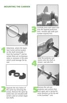
Determine where the Spare Seal Carrier will be located certain there are no keyways, nicks or corrosion in this area which could damage the lip screws. Remove the spare lip seal(s)-two are included with carriers used on certain larger size shafts. Carefully press each spare seal onto the tapered protective cone -smooth side (with part number imprint) first. seal(s) onto the shaft as shown- seal side first. rotector and confirm that ach spare seal is facing the same direction as the lip seal
Open the catalog to page 8
SEAL REPLACEMENT Reassemble the Spare Seal Carrier housing over the lip seal(s) and around the shaft. The long shoulder should face away from the SureSeal™. Clean shaft between Spare Seal Carrier and SureSeal housing. Remove the screws and open the Spare Seal Carrier exposing Check to be sure the housing assembly screws. Properly installed, the Spare Seal Carrier should grip the shaft tightly and turn freely with from the front of the housing. passing over the replacement
Open the catalog to page 9
Separate the split retaining washer and remove it from the screw driver working alternately on opposite sides. Cut old seal off shaft with diagonal pliers. Carefully slide the new lip seal down the shaft and into the chamfered opening in the front Return the split retaining washer to the shaft in front of Fit the split retaining washer into its recess inside the cap. Slide cap and washer until they touch the lip seal. Align holes Alternately tighten cap screws in a criss-cross pattern, driving the lip seal into the opening. Seal is seated properly when
Open the catalog to page 10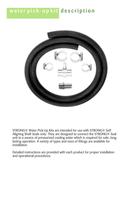
water pick-up kit description STRONG® Water Pick-Up Kits are intended for use with STRONG® Self Aligning Shaft Seals only. They are designed to connect the STRONG® Seal unit to a source of pressurized cooling water which is required for safe, longlasting operation. A variety of types and sizes of fittings are available for installation. Detailed instructions are provided with each product for proper installation and operational procedures.
Open the catalog to page 11
Heat Exchanger Water Pump 5 1 4 Riser Oil Cooler 5 2 3 NOTE: The preferred water pick-up point would be via a hose tee in the raw water discharge hose. Locate the tee AS CLOSE TO THE ENGINE AS POSSIBLE to insure adequate head pressure. 6 6 WATER PIC K-UP POI NTS: 1. Tee- In line between heat exchanger and riser (as close to heat exchanger as possible). 2. Tee- In line between oil cooler and heat exchanger. 3. Tee- In line between water pump and oil cooler. 4. Drain plug- Back of water pump. Be sure the drain is on the pressure side of the pump. 5. Drain plugs- In heat exchanger. 6. Drain plugs-...
Open the catalog to page 12
When using Straight Water Injection Fittings, carefully select a pick-up point on the engine, gear cooler, heat exchanger, etc. that optimizes water flow under a variety of conditions over time. DO NOT USE FITTI NGS SMALL ER THAN 1/4” NPT. The following is a list of things to consider when selecting a pick-up point for a Straight Water Injection Fitting: What will the pick-up point look like in three, four or five years? Will a manifold point clog with rust or scale? Will a heat exchanger pick-up point still provide water if the heat exchanger is not serviced regularly? If you select a drain...
Open the catalog to page 13All Tides Marine catalogs and brochures
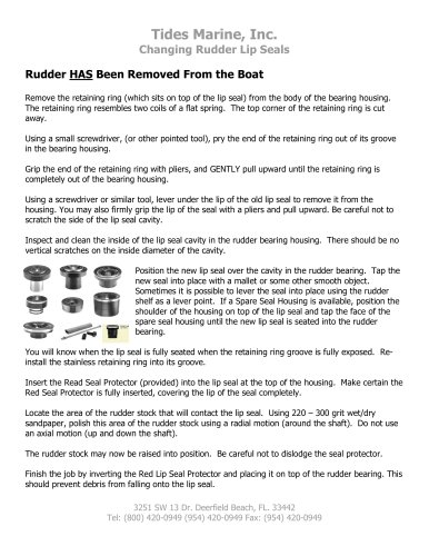 Replace Rudder Lip Seal
2 Pages
 TIDES CATALOG
88 Pages
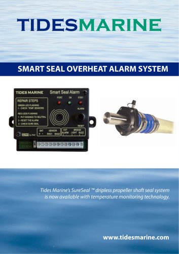 SMART SEAL ALARM SYSTEM
4 Pages

Archived catalogs
 Tides Marine Catalogue
90 Pages
 SureSeal Installation File
2 Pages
 SAIL TRACK SYSTEM
2 Pages
 SHAFT SEAL BROCHURE
12 Pages