- Catalogs
- Temposonics GmbH & Co. KG
- T-Series – TH CANbus
T-Series – TH CANbus
1 /15Pages
T-Series – TH CANbus
1 /15Pages
Catalog excerpts
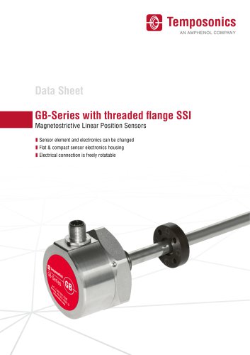
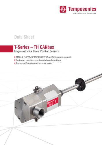
T-Series - TH CANbus Magnetostrictive Linear Position Sensors I ATEX/UK Ex/IECEx/CEC/NEC/CCC/PESO certified/Japanese approval I Continuous operation under harsh industrial conditions I Flameproof/Explosionproof/Increased safety
Open the catalog to page 1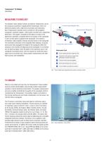
Temposonics® TH CANbus Data Sheet MEASURING TECHNOLOGY The absolute, linear position sensors provided by Temposonics rely on the company’s proprietary magnetostrictive technology, which can determine position with a high level of precision and robustness. Each Temposonics® position sensor consists of a ferromagnetic waveguide, a position magnet, a strain pulse converter and a supporting electronics. The magnet, connected to the object in motion in the application, generates a magnetic field at its location on the waveguide. A short current pulse is applied to the waveguide. This creates a momentary...
Open the catalog to page 2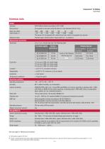
Data Sheet TECHNICAL DATA Output Resolution 2 pm, 5 pm; velocity step size: See following table For stroke lengths having a cycle time of Velocity step size at 5 pm position at 2 pm position resolution resolution See next page for “Mechanical mounting” 1/ With position magnet # 201 542-2 2/ If there is contact between the moving magnet (including the magnet holder) and the sensor rod, make sure that the maximum speed of the moving magnet is < 1 m/s (Safety requirement due to ESD [Electro Static Discharge])
Open the catalog to page 3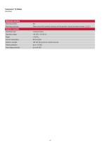
Data Sheet
Open the catalog to page 4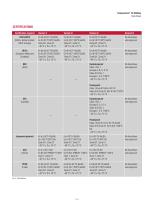
Data Sheet Certification required Version E Version D Version G Version N PESO Ex db eb IIC T4 Ga/Gb Ex db eb IIC T4 Ga/Gb Ex db eb IIC T4 Ga/Gb No hazardous (India) Ex tb IIIC T130°C Ga/Db Ex tb IIIC T130°C Ga/Db Ex tb IIIC T130°C Ga/Db area approval Zone 0/1, Zone 21 Zone 0/1, Zone 21 Zone 0/1, Zone 21
Open the catalog to page 5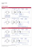
Temposonics® TH CANbus Data Sheet TECHNICAL DRAWING Threaded flange with raised-face Null zone 51 (2.01) 22.5 (0.89) Version D: A/F 55 Version G: A/F 60 Version G 82 (3.23) See order code section “d” for connection types Sensor electronics housing 112.5 (4.43) 2.5 (0.1) Sensor electronics housing 112.5 (4.43) Refer to “Table 1” for “TH rod sensor threaded flange type references” on page 7 Sensor electronics housing 132.5 (5.22) 2.5 “TH threaded flange type references” Referrod to sensor “Table 1” for “TH rod sensor threaded flange type references” on page 7 Strokelength length> >5000 5000mm mm(196.9...
Open the catalog to page 6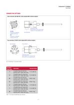
Data Sheet CONNECTION OPTIONSSide connection C01/N01/NF1 (with adapter)/M01 (without adapter) Side connection Top connection C10/N10 (with adapter)/M10 (without adapter) Top connection Top connection Fig. 5: Temposonics® TH connection options Threaded flange type Table 1: TH rod sensor threaded flange type references
Open the catalog to page 7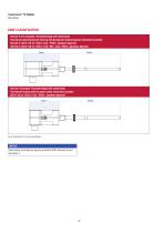
Temposonics® TH CANbus Data Sheet ZONE CLASSIFICATION Version D & G (example: Threaded flange with raised-face) Flameproof (explosionproof) housing with flameproof (explosionproof) connection chamber Version D: ATEX / UK Ex / IECEx / CCC / PESO / Japanese Approval Version G: ATEX / UK Ex / IECEx / CEC / NEC / CCC / PESO / Japanese Approval Zone 0 Version E (example: Threaded flange with raised-face) Flameproof housing with increased safety connection chamber ATEX / UK Ex / IECEx / CCC / PESO / Japanese Approval Zone 0 Fig. 6: Temposonics® TH Zone classification NOTICE Seal sensor according to...
Open the catalog to page 8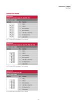
Data Sheet CONNECTOR WIRINGVersion D & G suitable for connection types: C01, C10, N01, N10 Signal + power supply CAN_L CAN_H Not connected Not connected +24 VDC (-15/+20 %) DC Ground (0 V) Cable shield Fig. 7: TH (version D & G) wiring diagram (2.5 mm2 conductor) Fig. 9: TH (version E & N) wiring diagram (2.5 mm2 conductor)
Open the catalog to page 9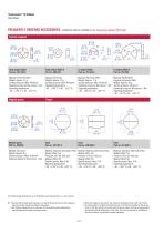
Temposonics® TH CANbus Data Sheet FREQUENTLY ORDERED ACCESSORIES – Additional options available in our Accessories Catalog Position magnets Ring magnet OD33 Part no. 201 542-2 Ring magnet OD25.4 Part no. 400 533 Material: PA ferrite GF20 Weight: Approx. 14 g Surface pressure: Max. 40 N/mm2 Fastening torque for M4 screws: 1 Nm Operating temperature: −40…+105 °C (−40…+221 °F) Material: PA ferrite Weight: Approx. 10 g Surface pressure: Max. 40 N/mm2 Operating temperature: −40…+105 °C (−40…+221 °F) Material: PA ferrite GF20 Weight: Approx. 11 g Surface pressure: Max. 40 N/mm2 Fastening torque for...
Open the catalog to page 10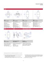
Data Sheet Stop collar for 0 10 mm Fixing clip Part no. 560 777 Part no. 561 481 Material: Stainless steel (AISI 316L) Pressure: 29.3 bar (425 psi) Specific gravity: Max. 0.67 Operating temperature: Provides end of stroke stops for float Material: Stainless steel 1.4301 (AISI 304) Weight: Approx. 30 g Hex key 7/64" required Application: Used to secure sensor rods (0 10 mm (0 0.39 in.)) when using an U-magnet or block magnet Material: Brass, non-magnetic Controlling design dimensions are in millimeters and measurements in () are in inches 4/ • Be sure that the float specific gravity is at least...
Open the catalog to page 11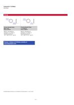
Temposonics® TH CANbus Data Sheet O-ring for threaded flange M18×1.5-6g Part no. 401 133 O-ring for threaded flange ¾"-16 UNF-3A Part no. 560 315 Material: Fluoroelastomer Durometer: 75 ± 5 Shore A Operating temperature: −40…+204 °C (−40…+400 °F) Material: Fluoroelastomer Durometer: 75 ± 5 Shore A Operating temperature: −40…+204 °C (−40…+400 °F) Manuals, Software & 3D Models available at: www.temposonics.com Controlling design dimensions are in millimeters and measure
Open the catalog to page 12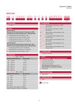
ORDER CODE Data Sheet
Open the catalog to page 13
Data Sheet • Specify magnet numbers for your sensing application and order separately. • The number of magnets is limited by the stroke length. • The minimum allowed distance between magnets (i.e. front face of one to the front face of the next one) is 75 mm (3 in.). • Use magnets of the same type for multi-position measurement. Accessories have to be ordered separately 6/ Please contact Temposonics if you are interested in further CAN protocols 7/ Note: Specify magnet numbers for your sensing application and order separately
Open the catalog to page 14All Temposonics GmbH & Co. KG catalogs and brochures
 Level Plus® – Tank SLAYER®
8 Pages
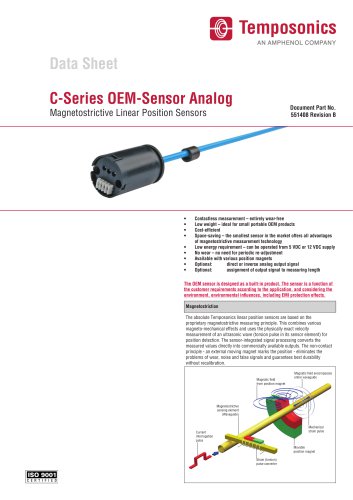 C-Series OEM-Sensor Analog
4 Pages
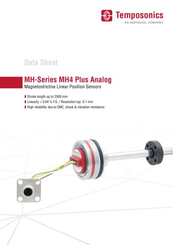 MH-Series MH4 Plus Analog
15 Pages
 T-Series – TH Analog
14 Pages
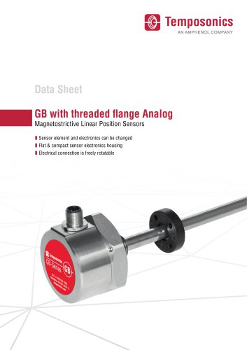 GB with threaded flange Analog
10 Pages
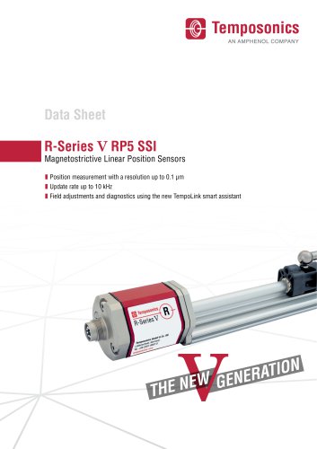 R-Series V RP5 SSI
12 Pages
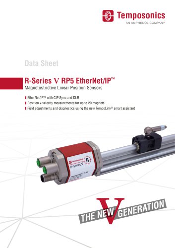 R-Series V RP5 EtherNet/IP ™
8 Pages