- Catalogs
- Temposonics GmbH & Co. KG
- T-Series – TH Analog
T-Series – TH Analog
1 /14Pages

T-Series – TH Analog
1 /14Pages
Catalog excerpts
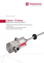
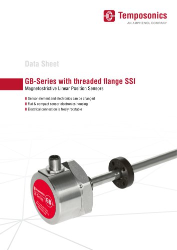
Data Sheet T-Series – TH Analog Magnetostrictive Linear Position Sensors ATEX/UK Ex/IECEx/CEC/NEC/KCs/CCC/PESO certified/Japanese approval/ ClassNK approval Continuous operation under harsh industrial conditions Flameproof/Explosionproof/Increased safety
Open the catalog to page 1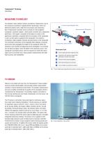
Temposonics® TH Analog Data Sheet MEASURING TECHNOLOGY The absolute, linear position sensors provided by Temposonics rely on the company’s proprietary magnetostrictive technology, which can determine position with a high level of precision and robustness. Each Temposonics® position sensor consists of a ferromagnetic waveguide, a position magnet, a strain pulse converter and a supporting electronics. The magnet, connected to the object in motion in the application, generates a magnetic field at its location on the waveguide. A short current pulse is applied to the waveguide. This creates a momentary...
Open the catalog to page 2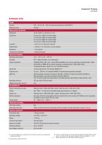
Data Sheet 1/ The internal digital value is transferred via a 16 bit D/A converter into a proportional, 3/ If there is contact between the moving magnet (including the magnet holder) and the analog current signal sensor rod, make sure that the maximum speed of the moving magnet is < 1 m/s I 3 I (Safety requirement due to ESD [Electro Static Discharge]) 2/ With position magnet # 201 542-2
Open the catalog to page 3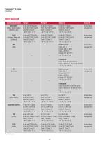
Data Sheet Certification required Version E Version D Version G Version N PESO Ex db eb IIC T4 Ga/Gb Ex db eb IIC T4 Ga/Gb Ex db eb IIC T4 Ga/Gb No hazardous (India) Ex tb IIIC T130°C Ga/Db Ex tb IIIC T130°C Ga/Db Ex tb IIIC T130°C Ga/Db area approval Zone 0/1, Zone 21 Zone 0/1, Zone 21 Zone 0/1, Zone 21
Open the catalog to page 4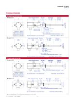
Temposonics® TH Analog Data Sheet TECHNICAL DRAWINGS Threaded flange with raised-face Null zone 51 (2.01) 22.5 (0.89) Version D: A/F 55 Version G: A/F 60 Version G 82 (3.23) See order code section “d” for connection types Sensor electronics housing 112.5 (4.43) 2.5 (0.1) Sensor electronics housing 112.5 (4.43) 22.5 Dead zone Null (0.89) zone Stroke length 63.5 (2.5)/ 51 25…7620 66* (2.6)* (2.01) (1…300) 22.5 (0.89) M18×1.5-6g: Ø 23.8 ± 0.2 (Ø 0.94 ± 0.01) A/F 55 ¾"-16 UNF-3A: Ø 25.4 ± 0.2 (Ø 1 ± 0.01) Refer to “Table 1” for “TH threaded flange type references” A/F 55 Referrod to sensor “Table...
Open the catalog to page 5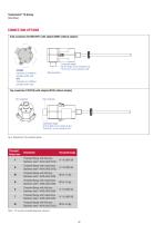
Data Sheet Side connection Top connection C10/N10 (with adapter)/M10 (without adapter) Top connection Top connection Fig. 5: Temposonics® TH connection options Threaded flange type Table 1: TH rod sensor threaded flange type references
Open the catalog to page 6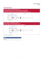
Temposonics® TH Analog Data Sheet ZONE CLASSIFICATION Version D & G (example: Threaded flange with raised-face) Flameproof (explosionproof) housing with flameproof (explosionproof) connection chamber Version D: ATEX / UK Ex / IECEx / KCs / CCC / PESO / Japanese Approval / ClassNK Approval Version G: ATEX / UK Ex / IECEx / CEC / NEC / KCs / CCC / PESO / Japanese Approval / ClassNK Approval Zone 0 Version E (example: Threaded flange with raised-face) Flameproof housing with increased safety connection chamber ATEX / UK Ex / IECEx / KCs / CCC / PESO / Japanese Approval / ClassNK Approval Zone 0...
Open the catalog to page 7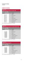
Data Sheet suitable for connection types: C01, C10, N01, N10 Signal + power supply Fig. 7: TH (version D & G) wiring diagram (2.5 mm2 conductor) Fig. 8: TH (version E & N) wiring diagram (1.5 mm2 conductor) suitable for connection type: NF1 Signal + power supply Fig. 9: TH (version E & N) wiring diagram (2.5mm2 conductor)
Open the catalog to page 8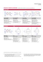
Temposonics® TH Analog Data Sheet FREQUENTLY ORDERED ACCESSORIES – Additional options available in our Accessories Guide Position magnete Ring magnet OD33 Part no. 201 542-2 Ring magnet OD25.4 Part no. 400 533 Material: PA ferrite GF20 Weight: Approx. 14 g Surface pressure: Max. 40 N/mm2 Fastening torque for M4 screws: 1 Nm Operating temperature: −40…+105 °C (−40…+221 °F) Material: PA ferrite Weight: Approx. 10 g Surface pressure: Max. 40 N/mm2 Operating temperature: −40…+105 °C (−40…+221 °F) Material: PA ferrite GF20 Weight: Approx. 11 g Surface pressure: Max. 40 N/mm2 Fastening torque for M4...
Open the catalog to page 9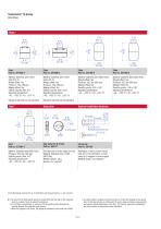
Data Sheet Material: Stainless steel 1.4571 (AISI 316 Ti) Weight offset: Yes Pressure: 4 bar (60 psi) Magnet offset: Yes Specific gravity: Max. 0.6 Operating temperature: -40...+125 °C (-40...+257 °F) Material: Stainless steel 1.4571 (AISI 316 Ti) Weight offset: Yes Pressure: 4 bar (60 psi) Magnet offset: Yes Specific gravity: 0.93 ± 0.01 Operating temperature: -40...+125 °C (-40...+257 °F) Material: Stainless steel (AISI 316L) Weight offset: Yes Pressure: 29.3 bar (425 psi) Magnet offset: No Specific gravity: 0.93 ± 0.01 Operating temperature: Material: Stainless steel (AISI 316L) Weight offset:...
Open the catalog to page 10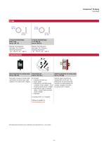
Temposonics® TH Analog Data Sheet O-ring for threaded flange M18×1.5-6g Part no. 401 133 O-ring for threaded flange ¾"-16 UNF-3A Part no. 560 315 Material: Fluoroelastomer Durometer: 75 ± 5 Shore A Operating temperature: −40…+204 °C (−40…+400 °F) Material: Fluoroelastomer Durometer: 75 ± 5 Shore A Operating temperature: −40…+204 °C (−40…+400 °F) Programming tools Hand programmer for analog output Part no. 253 124 Cabinet programmer for analog output Part no. 253 408 Easy teach-in-setups of stroke length and direction on desired zero / span positions. For sensors with 1 magnet. Kit includes: 1 ×...
Open the catalog to page 11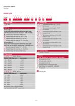
Data Sheet Standard stroke length (mm) Ordering steps Side connection with thread W-14 NPT (All versions) Top connection with thread W-14 NPT (All versions) Side connection with thread M16x1.5-6H (Version E & N) Top connection with thread M16x1.5-6H (Version E & N) Side connection with thread M20x1.5-6H (All versions) Top connection with thread M20x1.5-6H (All versions) Side connection with thread M20x1.5-6H (Version E & N) Standard stroke length (in.) Ordering steps Non Standard stroke lengths are available; must be encoded in 5 mm/0.1 in. increments.
Open the catalog to page 12All Temposonics GmbH & Co. KG catalogs and brochures
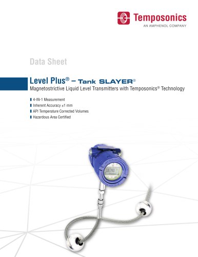 Level Plus® – Tank SLAYER®
8 Pages
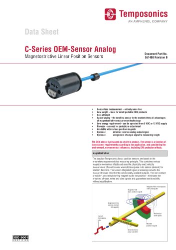 C-Series OEM-Sensor Analog
4 Pages
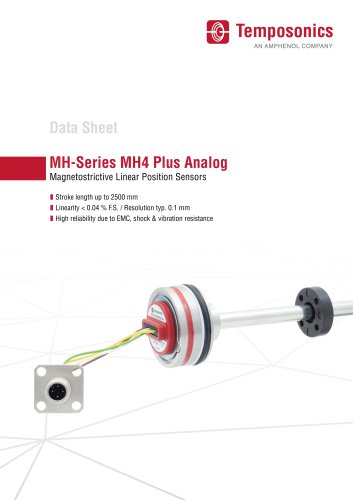 MH-Series MH4 Plus Analog
15 Pages
 T-Series – TH CANbus
15 Pages
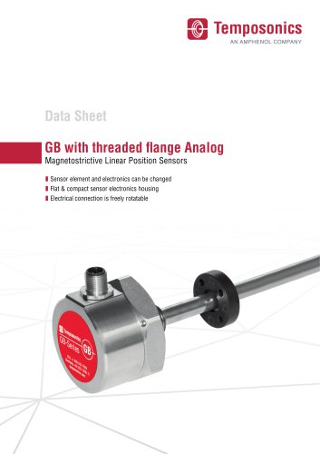 GB with threaded flange Analog
10 Pages
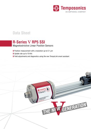 R-Series V RP5 SSI
12 Pages
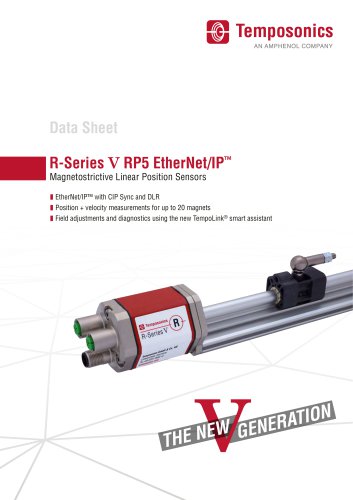 R-Series V RP5 EtherNet/IP ™
8 Pages