- Catalogs
- Temposonics GmbH & Co. KG
- MH-Series MH4 Plus Analog
MH-Series MH4 Plus Analog
1 /15Pages
MH-Series MH4 Plus Analog
1 /15Pages
Catalog excerpts
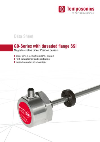
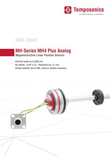
MH-Series MH4 Plus AnalogMagnetostrictive Linear Position Sensors I Stroke length up to 2500 mm I Linearity < 0.04 % F.S. / Resolution typ. 0.1 mm I High reliability due to EMC, shock & vibration resistance
Open the catalog to page 1
Temposonics® MH-Series MH4 Plus Analog Data Sheet The absolute, linear position sensors provided by Temposonics rely on the company’s proprietary magnetostrictive technology, which can determine position with a high level of precision and robustness. Each Temposonics® position sensor consists of a ferromagnetic waveguide, a position magnet, a strain pulse converter and a supporting electronics. The magnet, connected to the object in motion in the application, generates a magnetic field at its location on the waveguide. A short current pulse is applied to the waveguide. This creates a momentary...
Open the catalog to page 2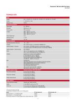
Data Sheet Measured value Position Stroke length Resolution Power up time Linearity Internal sample rate Setpoint tolerance Repeatability Operating conditions Operating temperature electronics -40...+105 °C Humidity 90 % relative humidity, no condensation, EN60068-2-30 Ingress protection - Connector M12 connector: IP67/IP69K (connectors correctly fitted), EN60529 DT connector system: IP67/IP69K (connectors correctly fitted), EN60529 Ingress protection - Sensor housing IP67, EN60529 Shock 100 g (11 ms) single shock per axis, IEC 60068-2-27 Vibration Operational sine vibration test IEC 60068-2-6:...
Open the catalog to page 3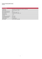
Electrical connection Connection type M12 connector or DT connector system or single wires or cable output Operating voltage 12/24 VDC nominal (8...32 VDC) Min Load resistance (output VDC) 10 kfi Max Load resistance (output mA) 250 fi (500 fi if supply > 13 V) Max Inrush current 4.5 A/2 ms (2.5 A/2 ms if supply < 13 V) Supply voltage ripple < 1 % PP Over voltage protection (GND-VDC) Up to +36 VDC Polarity protection (GND-VDC) Up to -36 VDC Electric strength 500 VDC (DC GND to chassis GND)
Open the catalog to page 4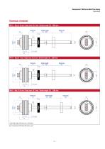
Temposonics® MH-Series MH4 Plus Analog Data Sheet TECHNICAL DRAWING MH-C – Rod: Ø 10 mm / Dead zone: 63.5 mm / Stroke length: 50…2500 mm Null zone 30 MH-D – Rod: Ø 7 mm / Dead zone: 63.5 mm / Stroke length: 50…2500 mm Null zone 30 MH-E – Rod: Ø 10 mm / Dead zone: 36.5 mm / Stroke length: 50…1200 mm Null zone 30 30 Controlling design dimensions are in millimeters Fig. 4: Temposonics® MH-Series MH sensor, part 1
Open the catalog to page 5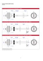
Temposonics® MH-Series MH4 Plus Analog Data Sheet MH-F – Rod: Ø 7 mm / Dead zone: 36.5 mm / Stroke length: 50…1200 mm Null zone 30 MH-L – Rod: Ø 10 mm + end plug with female M6 thread / Dead zone: 69.5 mm / Stroke length: 50…2500 mm Null zone 30 MH-R – Rod: Ø 10 mm + end plug with female M4 thread / Dead zone: 69.5 mm / Stroke length: 50…2500 mm Null zone 30 Controlling design dimensions are in millimeters Fig. 5: Temposonics® MH-Series MH sensor, part 2
Open the catalog to page 6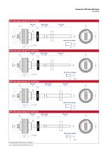
Temposonics® MH-Series MH Analog Data Sheet MH-C with conical end plug “K1” for Ø 10 mm Null zone 30 Detail view of endplug +0 21.2 −0.2 30 MH-D with conical end plug “K1” for Ø 7 mm Null zone 30 Detail view of endplug +0 21.2 −0.2 30 MH-E with conical end plug “K1” for Ø 10 mm Null zone 30 Detail view of endplug +0 21.2 −0.2 30 MH-F with conical end plug “K1” for Ø 7 mm Null zone 30 Detail view of endplug +0 21.2 −0.2 30 Controlling design dimensions are in millimeters Fig. 6: Temposonics® MH-Series MH senso
Open the catalog to page 7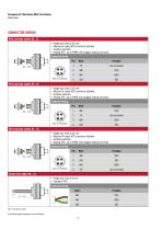
Temposonics® MH-Series MH4 Plus Analog Data Sheet CONNECTOR WIRING M12 connector system (N…E) • • • • Single lead wires 0.22 mm2 Attached A-coded M12 connector attached Toolless assembly Sealing IP67, up to IP69K with plugged mating connector Connector wiring Single lead wires 0.22 mm2 Attached A-coded M12 connector attached Toolless assembly Sealing IP67, up to IP69K with plugged mating connector Connector wiring Single lead wires 0.22 mm2 Attached A-coded M12 connector attached Toolless assembly Sealing IP67, up to IP69K with plugged mating connector Connector wiring Single wires pigtail (N…A)...
Open the catalog to page 8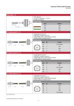
Data Sheet 0 5 mm, non-shielded, 3 x 0.5 mm2 Flexible, oil resistance DT connector system E (A...E) DT connector system G (A...G) DT connector system H (A...H) • Single lead wires 0.22 mm2 • Attached DT compatible connector • Sealing IP69K (with or without mating connector) • Wiring sequence controlled at sensor • Single lead wires 0.22 mm2 • Attached DT compatible connector • Sealing IP69K (with or without mating connector) • Wiring sequence controlled at sensor • Single lead wires 0.22 mm2 • Attached DT compatible connector • Sealing IP69K (with or without mating connector) • Wiring sequence...
Open the catalog to page 9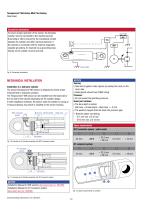
Temposonics® MH-Series MH4 Plus Analog Data Sheet Connection schematics To ensure proper operation of the sensor, the hydraulic cylinder must be connected to the machine ground. Grounding is oftern ensured by the machanical contact between the cylinder and other machine elements. If the cylinder is connected with the machine separately, separate grounding, for example via a grounding strap directly on the cylinder must be ensured. Chassis GND Fig. 9: Connection schematics MECHANICAL INSTALLATION NOTICE Sealing: • Take action against water ingress by sealing the cavity on the cover side. • Cable...
Open the catalog to page 10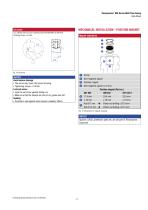
Temposonics® MH-Series MH4 Plus Analog Data Sheet MECHANICAL INSTALLATION - POSITION MAGNET Magnet installation Avoid sensor damage: • The screw may touch the sensor housing. • Lock the set screw against falling out. • Make sure that the threads are free of oil, grease and dirt. • Consider a seal against water ingress (capillary effect). © Non-magnetic spacer © Position magnet © Non-magnetic spacer (> 5 mm) Position magnet (Part no.) Controlling design dimensions are in millimeters Fig. 14: Dimensions for magnet mounting NOTICE Spacers, circlip, pretension parts etc. are not part of Temposonics...
Open the catalog to page 11All Temposonics GmbH & Co. KG catalogs and brochures
 Level Plus® – Tank SLAYER®
8 Pages
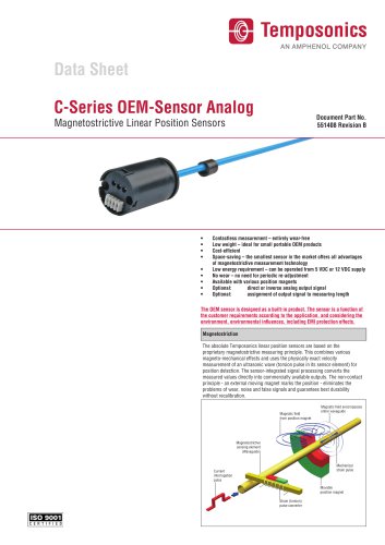 C-Series OEM-Sensor Analog
4 Pages
 T-Series – TH CANbus
15 Pages
 T-Series – TH Analog
14 Pages
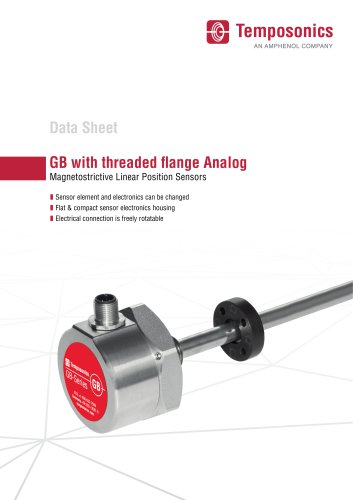 GB with threaded flange Analog
10 Pages
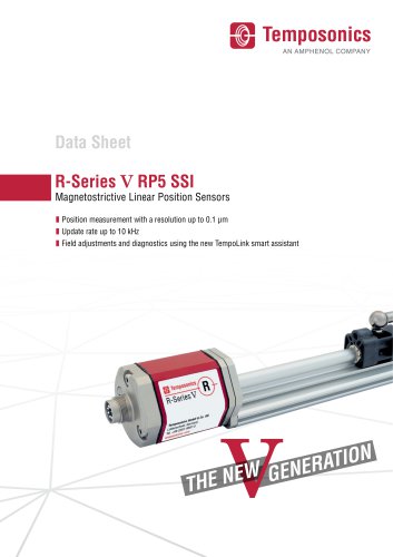 R-Series V RP5 SSI
12 Pages
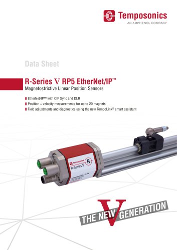 R-Series V RP5 EtherNet/IP ™
8 Pages