CM - Cam Lock Latches

CM - Cam Lock Latches
- Removable Core Options: These offer maximum flexibility with multiple key codes, tool actuation, and future reconfiguration capabilities. They are ideal for applications requiring diverse key codes or tool-actuated options. Sealed versions meet NEMA 4 and IP65 standards.
- Fixed Core Options: These provide simple, economic solutions with key-locking and wing driver options. They are available in sealed and non-sealed versions, with the sealed version meeting NEMA 4 and IP65 standards.
- Cam Lock Selection Guide: A step-by-step guide to selecting the appropriate CM Cam Lock components based on cam grip, door thickness, and housing length. It includes instructions for determining cam orientation and length.
- Material and Finish: Housing is made of zinc alloy, available in chrome plated or black powder coated finishes. Non-sealed versions have a stainless steel scalp.
- Performance Details: The average ultimate load on the cam is 180 N (40 lbf). Installation notes and accessory options are provided for optimal setup.
- Accessories and Spare Parts: Includes keys, dust covers, pull tabs, washers, and mounting components. Specific part numbers and materials are listed for each accessory.
- All components are ordered separately to allow for maximum configuration flexibility.
- Sealed versions are designed to meet specific water intrusion standards, ensuring durability in various environments.
- Multiple finishes and housing sizes are available to suit different aesthetic and functional requirements.
Catalog excerpts
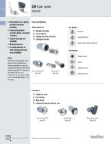
• Removable core options provide maximum flexibility • Fixed core options provide simple, economic solutions • Sealed housings are available • Multiple finishes • A broad selection of lock housing and cam sizes available Cam Lock Options Removable Core ÂÂ ÂÂ ÂÂ ÂÂ Multiple key codes Tool actuation Change key codes in future Configure to order Key alike Keyed differently Master keyed, keyed differently Tool Options Phillips recess Notes All CM Cam Lock housings, cams, and lock core components are ordered separately for maximum configuration flexibility with minimal inventory investment. To determine Non Sealed CM-6 the perfect CM Cam Lock Page 188 components for your needs, simply follow the Selection Guide on the next page. Slotted 4mm Hex recess Sealed CM-3 Page 188 Single key code Key-locking Wing driver Integrated housing and lock core Dimensions in millimeters (inch) unless otherwise stated Wing Driver CM-1 Page 190
Open the catalog to page 1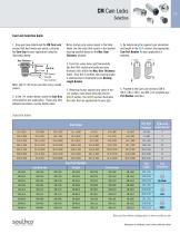
Cam Lock Selection Guide 1. Once you have determined the CM Cam Lock version that best meets your needs, calculate the Cam Grip for your application using the illustration below. Notes: Certain grip values repeat in the table below. Use the value that results in the shortest housing possible based on the Max. Door Thickness allowed. 5. By determining the required cam orientation and length in the BLUE section, the appropriate Cam Part Number for your application is selected. Length Door Thickness Cam Grip Frame Cam forward Straight Cam reversed Notes: add 0.5 (.02) to your grip when using a sealed...
Open the catalog to page 2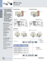
Removable core • Ideal for applications requiring multiple key codes or tool actuated options • Sealed version meets NEMA 4 and IP65 water intrusion standards • Lock cores and cams sold separately • Master and non-master key codes available Material and Finish Housing: Zinc alloy, chrome plated or black powder coated Scalp: stainless steel (non-sealed only) Sealed Disc Tumbler Non-Sealed Disc Tumbler ACTUAL SIZE Sealing washer compressed height 0.5 (.02) Cam forward Straight cam Cam reversed Performance Details Cam Locked Position forward 7 (.28) Unlocked Position Straight cam Lock extender Cam...
Open the catalog to page 3
Fixed core Sealed Disc Tumbler Non-Sealed Disc Tumbler ACTUAL SIZE Sealing washer compressed height 0.5 (.02) Cam forward Straight cam Cam reversed Cam grip Frame Cam Locked Position forward Straight cam Cam reversed • Stainless steel scalp on housing and lock core on non-shuttered style • Sealed version meets NEMA 4 and IP65 water intrusion standards • Cams sold separately Material and Finish Housing: Zinc alloy, chrome plated or black powder coated Scalp: stainless steel (non-sealed only) Performance Details Average ultimate load on cam: 180 N (40 lbf) Installation Notes See page 191 Cam Rotation...
Open the catalog to page 4
Fixed core wing driver • Sealed to meet NEMA 4 and IP65 water intrusion standards • Smooth, consistent operation • Cams sold separately ACTUAL SIZE Material and Finish Housing: Zinc alloy, chrome plated or black powder coated Performance Details Sealing washer compressed height 0.5 (.02) Average ultimate load on cam: 180 N (40 lbf) Installation Notes Locked Position Unlocked Position Cam forward R 01 (Clockwise) Unlocked Position Part Number Selection Lock part number (no cam) Order lock and cam separately Cam page 191 To select cam part number see grip table page 187 Locked Position Unlocked...
Open the catalog to page 5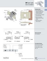
Cams & installation Sealing washer (if included) Installation Notes 1. Place sealing washer onto housing (if included) and put through the mounting hole (see panel preparation). Housing Door 2. Install mounting nut and tighten to 5 Nm (44 inlbf). Screw & lock washer Stop washer 3. Install cam to assembly Properly orientate for rotation and grip. 4. Install screw. Tighten to 4 Nm (35 inlbf). Max. door thickness (see table page 187) Material and Finish Cam: Steel plated Part Number Selection S Style C No hook H Hook type 1 L Hook type 2 Order lock and cam separately Cam part number (no lock) For...
Open the catalog to page 6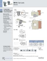
Fixed core • Compact design • Non-shuttered lock core • Cams sold separately Material and Finish Lock: Zinc alloy, chrome plated or black powder coated Cam: Steel, zinc plated Cam offset forward ACTUAL Straight cam Performance Details Average ultimate load on cam: 160 N (35 lbf) Installation Notes 1. Install mounting nut and tighten to 4 Nm (35 inlbf). 2. Install cam to assembly. Properly orientate for rotation and grip. 3. Install screw. Tighten to 4 Nm (35 inlbf). Part Number Selection Lock part number (no cam) Order lock and cam separately To select cam part number see grip table above F Housing...
Open the catalog to page 7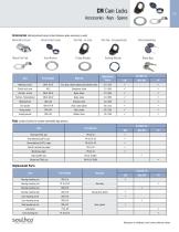
Accessories • Keys • Spares Accessories (Add adjustment value to door thickness when accessory is used) Metal Dust Cover Plastic Dust Cover Pull Tab - In-Line Trim Washer Prong Washer Sealing Washer CONNECT ■ CREATE ■ INNOVATE Dimensions in millimeters (inch) unless otherwise stated
Open the catalog to page 8All Southco catalogs and brochures
 M1 Push-to-Close Latch
4 Pages
 R4 - Rotary Latches
12 Pages
 R4-EM 9 Series
4 Pages
 H3 Swinghandle System
5 Pages
 ST series
7 Pages
 AC - Cables
4 Pages
 C2 - Lever Latches
1 Page
 C7 Draw Latch
1 Page
 C3 Push-to-Close Latch
3 Pages
 A7 Compression Latch
2 Pages
 E3 VISE ACTION
28 Pages
 AV - Tilt Mount (T Series)
4 Pages
 MP - Pulls
1 Page
 P8 - Wire Pull Handles
1 Page
 B8 - Grab Handles
2 Pages
 M5 - Lift Handles
1 Page
 B4 - Lightweight Handles
1 Page
 MP - Coat Hook
1 Page
 P1 - Flush Pull
1 Page
 67 - Concealed Pulls
2 Pages
 PT - Tubular Key Cam Lock
2 Pages
 PK - Lock Plugs
2 Pages
 10/38 - Drive Rivets
3 Pages
 GA - Gaskets
1 Page
 MT
MT1 Page
 DRAINS
4 Pages
 THRU HU LLS
5 Pages
 DECK FILLS & TANK VENTS
6 Pages
 Rod holder
3 Pages
 Other Deck Hardware
8 Pages
 Eyes
Eyes5 Pages


Archived catalogs
 Push-to-Close Latch
4 Pages
 E5 TROLLER Cam LATCH
1 Page
 Cleats chocks
8 Pages
 Lighting electrical
2 Pages
 Drains
10 Pages
 Deckfills TankVents
10 Pages
 TruHulls
7 Pages
 Deck Hardware
138 Pages
 Access Hardware
84 Pages

