


- Products
- Catalogs
- News & Trends
- Exhibitions
C3 Push-to-Close Latch

C3 Push-to-Close Latch
The document provides detailed specifications for the C3 Push-to-Close Latch, including dimensions in millimeters (inches) and pull-up force options. The latch is available in three pull-up force variants: 13 N (3 lbf) with a blue spring, 22 N (5 lbf) with a silver spring, and 44 N (10 lbf) with a black spring. Part numbers vary based on the pull-up force and frame thickness range.
Procedures:
Installation involves using M3 or No. 4 size screws or Ø 3 rivets for mounting. The document specifies the orientation of the keeper to the latch, with an arrow indicating the correct direction towards the cam. The installation requires adjusting for smooth latching and ensuring the minimum distance from the frame to the door hinge is 150 mm (5.9 inches).
Standards and Performance:
The latch is designed for non-safety related logic circuits and is not intended as a safety interlock. It operates within a temperature range of -40ºC (-40ºF) to 60ºC (140ºF) and has a flammability rating of UL94-V0 or UL94-HB depending on the material. The switch is VDE and UL approved, with a maximum AC voltage of 250V and current of 6A.
Material and Finish:
The latch is made from PC/ABS, black and glass-filled nylon, or mineral-filled nylon, all in black.
Installation Notes:
Maximum tightening torque for mounting screws is specified as 1.1 N·m (9.7 in·lbf) for the catch and 2.8 N·m (24.8 in·lbf) for the keeper. The terminal cover is for shipping protection only, and strain relief should be used on wires.
Additional Information:
The document includes diagrams and tables detailing dimensions, part numbers, and installation instructions. It emphasizes the importance of correct orientation and adjustment for optimal performance.
Catalog excerpts

Pull-to-open · Grabber catch with integral Microswitch Terminal detail ACTUAL SIZE Performance Details Operating temperature range: -40ºC (-40ºF) to 60ºC (140ºF) Installation Notes Switch specification. Subminiature VDE, UL approved. Switch is fitted with fast-on terminals. Max AC voltage 250V, max AC current 6A. See graph below for DC resistive load. Current DC (amps) Two holes Ø 3.3 +0.1 (.130 +.004 ) -0 -0 for M3 or No. 4 size screws or Ø 3 rivets THIS 6 PRODUCT IS SPECIFICALLY DESIGNED TO BE USED AS A MECHANICAL GRABBER CATCH WITH AN Frame 1 ELECTRIC SWITCH. THE SWITCH IS DESIGNED TO OPERATE AN INDICATOR LIGHT OR FORM PART OF A NON-SAFETY RELATED LOGIC CIRCUIT. NOT DESIGNED FOR USE AS A SAFETY INTERLOCK. .75 TERMINAL COVER IS USED FOR PROTECTION DURING SHIPPING ONLY. USE STRAIN RELIEF ON WIRES. .5 Centerline of .25 frame holes 0 25 50 75 125 250 0±0.2 40.6 +0.3 -0 (0±.008) +.012 Volts DC (1.60 - 0 ) Over 50 V DC, inductive loads should be greatly reduced Right Side Installation Shown Invert catch and keeper for left side installation Material and Finish PC/ABS, black and glass-filled nylon, black • Opens and closes switch contacts with door operation • One assembly includes catch and keeper • Spring loaded over-center latching Centerline of door holes 55±0.5 (2.165±.020) Max. tightening torque on mounting screws (not supplied): Catch 1.1 Nm (9.7 inlbf) Keeper 2.8 Nm (24.8 inlbf) Orient keeper to latch. The arrow on the keeper should point towards the cam. Mount to door and adjust for smooth latching. Note: These holes and dimensions are used only if adjustability through the use of slotted holes in catch is desired. Connection is live when latch is closed Connection is live when latch is open Approximate Pull-Up Force Spring Color Part Number This product is specifically designed to be used as a mechanical grabber catch with an electric switch. The switch is designed to operate an indicator light or form part of a non-safety related logic circuit. This is not designed for use as a safety interlock. Terminal cover is used for protection during shipping only. Use strain relief on wires. Min. distance from frame (or surface on which catch subassembly is mounted) to centerline of door hinge is 150 (5.9) Dimensions in millimeters (inch) unless otherwise stated Part Number See table
Open the catalog to page 1
Pull-to-open · Grabber catch · Snap-in • Spring-loaded over-center latching • One assembly includes catch and keeper Keeper 4.3 (.17) Orientation indicators Material and Finish PC/ABS, black and glass-filled nylon, black, mineral filled nylon, black Performance Details Operating temperature range: -30ºC (-20ºF) to 60ºC (140ºF) Installation Notes Max. tightening torque on mounting screws (not supplied) Keeper: 2.8 Nm (24.8 inlbf) Orient keeper to latch. The arrow on the keeper should point towards the cam. Mount to door and adjust for smooth latching ACTUAL SIZE 2.5±0.3 (.098±.012) Optional panel...
Open the catalog to page 2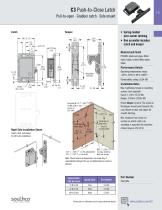
Pull-to-open · Grabber catch · Side mount • Spring-loaded over-center latching • One assembly includes catch and keeper PC/ABS, black and glass-filled nylon, black, mineral filled nylon, black Performance Details Operating temperature range: -30ºC (-20ºF) to 60ºC (140ºF) Orientation indicator ACTUAL SIZE Installation Notes Two holes Ø 3.3 +0.1 (.130 +.004 ) -0 -0 for M3 or No. 4 size screws or Ø 3 rivets Frame Centerline of frame holes Right Side Installation Shown Invert catch and keeper for left side installation Max. tightening torque on mounting screws: (not supplied) Catch: 1.1 Nm (9.7inlbf)...
Open the catalog to page 3All Southco catalogs and brochures
 M1 Push-to-Close Latch
4 Pages
 R4 - Rotary Latches
12 Pages
 R4-EM 9 Series
4 Pages
 H3 Swinghandle System
5 Pages
 ST series
7 Pages
 AC - Cables
4 Pages
 C2 - Lever Latches
1 Page
 C7 Draw Latch
1 Page
 A7 Compression Latch
2 Pages
 E3 VISE ACTION
28 Pages
 AV - Tilt Mount (T Series)
4 Pages
 MP - Pulls
1 Page
 P8 - Wire Pull Handles
1 Page
 B8 - Grab Handles
2 Pages
 M5 - Lift Handles
1 Page
 B4 - Lightweight Handles
1 Page
 MP - Coat Hook
1 Page
 P1 - Flush Pull
1 Page
 67 - Concealed Pulls
2 Pages
 PT - Tubular Key Cam Lock
2 Pages
 PK - Lock Plugs
2 Pages
 CM - Cam Lock Latches
8 Pages
 10/38 - Drive Rivets
3 Pages
 GA - Gaskets
1 Page
 MT
MT1 Page
 DRAINS
4 Pages
 THRU HU LLS
5 Pages
 DECK FILLS & TANK VENTS
6 Pages
 Rod holder
3 Pages
 Other Deck Hardware
8 Pages
 Eyes
Eyes5 Pages




Archived catalogs
 Push-to-Close Latch
4 Pages
 E5 TROLLER Cam LATCH
1 Page
 Cleats chocks
8 Pages
 Lighting electrical
2 Pages
 Drains
10 Pages
 Deckfills TankVents
10 Pages
 TruHulls
7 Pages
 Deck Hardware
138 Pages
 Access Hardware
84 Pages

