
- Catalogs
- Soundown Corporation
- Exhaust Literature Final

- Products
- Catalogs
- News & Trends
- Exhibitions
Exhaust Literature Final

Exhaust Literature Final
- Ideal for low waterline installations with limited space.
- Inlet typically at lowest or highest point; outlets can be anywhere.
- Drain located at the lowest part of the shell.
- Available sizes range from 15kW/25hp to 2600hp with various inlet/outlet diameters.
- Options include flanged connections, custom elbows, and high-grade finishes.
- Exhaust components should be close together; drains should be 12” above waterline.
- Minimize bends and upward inclines in exhaust routing.
- Partial raw water bypass may be required.
- Suitable for high waterline installations.
- Inlets on end plate or side shell; outlets high on the opposite end.
- Available in cylindrical and elliptical shapes, with sizes up to 3600hp.
- Options similar to Classic Waterdrop Silencer.
- Silencer should be level and installed below dry riser or wet elbow.
- Minimize bends and upward inclines in exhaust routing.
- Available for power ratings from 15kW/25hp to 400kW/1000hp.
- Options include flanged connections and custom mounting rings.
- Ideal for high power propulsion engines.
- Inlets at upper canister; outlets towards underwater discharge.
- Available for power ratings up to 3600hp.
- Options include horizontal configurations and remote bypass locations.
- Designed for low waterline situations.
- Inlet in lower third, outlet in upper third of silencer body.
- Available for power ratings from 15kW/25hp to 400kW/1000hp.
- Soot Sinkers must be installed below DWL and vented to silencer.
- Soot Catchers use air bubbles to channel soot to a holding chamber.
- Available in various sizes with options for flanged connections and custom pipes.
- Wet exhaust systems can flood engines if improperly used or installed.
- Composite exhaust silencers are designed for temperatures below 90°C.
- Higher temperatures can increase backpressure and shorten service life.
Catalog excerpts

Soundown Exhaust Components Sizing and Configuration Guide 10/27/2008
Open the catalog to page 1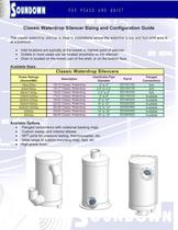
Classic Waterdrop Silencer Sizing and Configuration Guide The classic waterdrop silencer is ideal in installations where the waterline is low and foot print area i; • Inlet locations are typically at the lowest or highest point of silencer. • Outlets in most cases can be located anywhere on the silencer. • Drain is located on the lowest part of the shell, or on the bottom face. Available Sizes____ Custom sweep and mitered elbows NPT ports for pressure testing, thermocouples, etc. Wide range of custom mounting rings, feet, etc. High-grade finish.
Open the catalog to page 2
JoUNOOWN F0* peice **s QUIET Classic Waterdrop Generator Exhaust Installation Notes Generator Exhaust System • Keep exhaust components in close proximity to one another. • Drains should be minimum 12" above waterline. Drain should travel to min. 6" below DWL. All horizontal runs should be minimized and pitched. • Path from lift to silencer should be as direct as possible to minimize backpressure. • Minimize bends in the piping between lift & waterdrop. If silencers are offset from each other, rise from the lift then run to the waterdrop. • Minimize or eliminate bends and upward inclines in all...
Open the catalog to page 3
OUNDOWN F0* PEICE -|:: QUIET Classic Waterdrop Propulsion Exhaust Installation Notes Propulsion Exhaust System • Silencer to be installed level. • Silencer to be below dry riser or wet elbow. • Minimize or eliminate bends and upward inclines in all exhaust pipe routing. • Drain piping must nol be restricted in cross sectional area along the route to discharge. • Partial raw water bypass is a potential requirement of all exhaust systems.
Open the catalog to page 4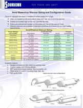
JoUNOOWN F0* peice **s QUIET Axial Waterdrop Silencer Sizing and Configuration Guide The axial silencers are ideal in installations where water line is high. • Inlets are located on the end plate or side shell near one end of the silencer. * Outlets are located high on the end opposite the inlet. • Drains are optional and located on the outlet end, low on the silencer body. • Elliptical silencers are available if standard cylindrical dimensions do not meet spatial Available Options • Flanged connections with rotational backing rings. • Custom sweep and mitered elbows • NPT ports for pressure...
Open the catalog to page 5
OUNDOWN F0* PEICE -|:: QUIET Axial Generator Exhaust Installation Notes Generator Exhaust System • Silencer to be installed level. • Keep exhaust components in close proximity to one another. • Drains should be minimum 12" above waterline. Drain should travel to min. 6" below DWL. All horizontal runs should be minimized and pitched. • Path from lift to silencer should be as direct as possible to minimize backpressure. • Minimize bends in the piping between lift & waterdrop. If silencers are offset from each other, rise from the lift then run to the waterdrop. • Minimize or eliminate bends and...
Open the catalog to page 6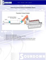
Axial Propulsion Exhaust Installation Notes Axial Waterdrop Silencer— Propulsion Exhaust System Silencer to be installed level. Silencer to be installed below dry riser or wet elbow Silencer to be installed at or above DWL. Minimize or eliminate bends and upward inclines in all exhaust pipe routing. Partial raw water bypass is a potential requirement for all exhaust systems.
Open the catalog to page 7
OUNDOWN F0" FEICE -|:: QUIET Water Lifts Sizing and Configuration Guide Available Sizes Available Options • Flanged connections with rotational backing rings. • Custom sweep and mitered elbows • NPT ports for pressure testing, thermocouples, etc. • Wide range of custom mounting rings, feet, etc. • High-grade finish.
Open the catalog to page 8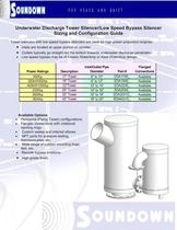
OUNDOWN F0* PEICE -|:: QUIET Underwater Discharge Tower Silencer/Low Speed Bypass Silencer Sizing and Configuration Guide Tower silencers with low speed bypass silencers are ideal for high power propulsion engines. • Inlets are located at upper portion of canister. • Outlets typically go straight out the bottom towards underwater discharge penetration. • Low speed bypass may be of Classic Waterdrop or Axial Waterdrop design. Available Options • Horizontal (Flying Tower) configurations. • Flanged connections with rotational backing rings. • Custom sweep and mitered elbows • NPT ports for pressure...
Open the catalog to page 9
Underwater Discharge Tower Silencer/Low Speed Bypass Silencer Sizing and Configuration Guide • • • • • • • Silencer to be installed level. Silencer to be installed below dry riser or wet elbow Silencer to be installed at or above DWL. Minimize or eliminate bends and upward inclines in all exhaust pipe routing. Drain piping must not restrict in area along the route to discharge. Partial raw water bypass is a around silencer system is a potential requirement of all systems. Drain piping must not be restricted in cross sectional area along the route to discharge. 10/27/2008
Open the catalog to page 10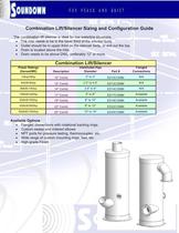
Combination Lift/Silencer Sizing and Configuration Guide The combination lift silencer is ideal for low waterline situations. • The inlet needs to be in the lower third of the silencer body. • Outlet should be in upper third on the silencer body, or exit out the top. • Drain is located above the inlet. • Drain needs to be above DWL, preferably 12” or more. Combination Lift/Silencer Power Ratings (Genset/ME) Description Inlet/Outlet Pipe Diameter Part # Flanged Connections 15kw/25hp 10" Combi 2" to 3" ED10COMBI N/A 40kW/60hp 12" Combi 2.5" to 4.5" ED12COMBI N/A 90kW/140hp 14" Combi 3.5" to 6"...
Open the catalog to page 11
Combination Lift/Silencer Exhaust Installation Notes • • • • • • • • Silencer to be installed level. Keep exhaust components in close proximity to one another. Drains should be minimum 12” above waterline. Drain should travel to min. 6” below DWL. All horizontal runs should be minimized and pitched. Path from lift to silencer should be as direct as possible to minimize backpressure. Minimize bends in the piping between lift & waterdrop. If silencers are offset from each other, rise from the lift then run to the waterdrop. Minimize or eliminate bends and upward inclines in all exhaust pipe routing....
Open the catalog to page 12All Soundown Corporation catalogs and brochures
 FireMaster607 Blanket
2 Pages
 Rockwoll Firebatt
2 Pages
 Soundown
3 Pages
 Damping Tiles
2 Pages
 Sylomer
2 Pages
 Microlite
1 Page
 Hull board
1 Page
 QuieTech Perforated Aluminum
2 Pages
 Tuff Mass
2 Pages
 Acoustic Absorp Foam
2 Pages
 Polyimide Cut Sheet2009
2 Pages
 QuietCore 2010.1.A
2 Pages
Archived catalogs
 DC-3 Damping Compound
2 Pages
 Quiet Pro Tech
2 Pages
 Carpet underlayment
2 Pages
 Promaguard
2 Pages
 Vinyl foam insulation
2 Pages
 Soundown Product Guide
4 Pages
 Soundown Brochure
3 Pages
