

Sonihull DUO Installation Manual

Sonihull DUO Installation Manual
The Sonihull ultrasonic anti-fouling system is designed to protect vessels from bio-fouling such as algae, weeds, and molluscs. This manual provides guidance on installation and operation, emphasizing the importance of reading the printed instructions and consulting the Sonihull app for additional support.
Sonihull is compatible with materials like steel, aluminium, stainless steel, titanium, FRP & GRP composites, and rigid plastics. It is crucial to consult a professional marine technician if the vessel is made from FRP or GRP Sandwich Construction.
Electrical installation should be performed by a qualified Marine Electrician. The control box must be mounted in a dry location, with AC connections following Wiring Regulations and DC connections via a 5A breaker. Mains power cable color codes are provided for reference.
The system is warranted for 12 months, extendable by another 12 months upon online registration. It operates at 115/230V AC or 13-30V DC, with specific power consumption and IP ratings for the control box and transducers. The system includes a built-in AC Voltage Selector Switch and a DC Power Warning Feature.
Installation involves planning the layout, preparing surfaces, bonding transducer mounting rings, and connecting the control box to power supplies. Specific instructions are provided for different vessel components like hulls, keel coolers, waterjets, seachests, propellers, and box coolers.
Guidelines for fitting transducers include ensuring proper gel application, avoiding over-tightening, and preparing surfaces correctly. Detailed steps are provided for bonding transducer mounting rings to steel, aluminium, GRP, and FRP surfaces.
- Ensure the surface is flat, smooth, and clean before installation. Use isopropyl alcohol for cleaning.
- Protect screw threads with transducer gel to prevent epoxy contamination.
- Mix and apply epoxy to the base of the mounting ring, avoiding excess.
- Press the ring onto the prepared surface and allow the epoxy to cure for 12-24 hours.
- Apply transducer gel to the transducer contact face before screwing it into the mounting ring.
- Consult a marine technician before installation.
- Do not fit transducers to the inner layer of sandwich constructions.
- Remove the inner layer and some core material to reach the outer layer for bonding.
- Prepare the aluminium contact disk with epoxy and place it in the mounting ring.
- Ensure good contact between the disk and transducer contact face.
- Avoid overtightening to prevent damage.
- Choose the correct size adaptor and location, ensuring accessibility.
- Prepare the pipe surface by sanding for a smooth bonding surface.
- Apply epoxy to the pipe adaptor and secure it with zip ties or clips while curing.
- Apply transducer gel and screw the transducer into the adaptor without overtightening.
- Keel Cooler Adaptor: Provides contact between transducer and keel cooler pipes without plumbing.
- Pipe Adaptor: Suitable for various pipework to prevent bio-fouling.
- Offset (IPS) Adaptor: Allows ultrasonic transmission in hard-to-reach areas.
- Aluminium Mounting Ring: Ideal for larger aluminium structures.
Proper installation is critical for system effectiveness. The manual emphasizes the importance of following the detailed instructions and consulting professionals when necessary.
Catalog excerpts

INSTALLATION AND OPERATION MANUAL Manufactured by NRG Marine Ltd. Sonihull House, 9 Mercia Village Torwood Close, Westwood Business Park Coventry, CV4 8HX, United Kingdom Tel. +44 (0)2476 105 150 Fax +44 (0)8459 002 197 Email [email protected] Web www.sonihull.com © 2021 NRG MARINE. All Rights Reserved. [v.010621-2]
Open the catalog to page 1
Welcome to Sonihull Thank you for choosing the Sonihull ultrasonic anti-fouling system to protect your vessel from bio-fouling like algae, weeds and molluscs. In this manual we will guide you through the best practices for fitting your Sonihull system. Please read the printed fitting instructions before you start your installation. For further guidance, you can download the Sonihull app on your tablet or smartphone (Android and iOS devices supported). In the Sonihull app you will find fitting guides for all the items you can protect from marine bio-fouling. Everything from hulls, box coolers...
Open the catalog to page 2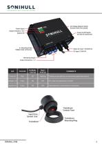
NORMAL STATUS FAULT STATUS OFF when not connected or in fault. Fault indication, check power & transducers. COMMENTS Flashing is normally due to incorrectly seated transducers.
Open the catalog to page 3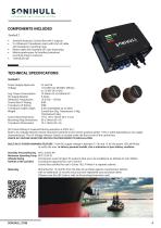
COMPONENTS INCLUDED Sonihull 2 Sonihull ultrasonic Control Box with 2 outputs 2 x Ultrasonic Transducers each with 6.5m of cable and transducer mounting rings Mains cable with standard UK 3-pin fused plug Marine grade epoxy for bonding transducer mounting rings to surfaces Transducer gel TECHNICAL SPECIFICATIONS Sonihull 2 Power Supply Approvals Voltage Avg. Power Consumption DC Supply Breaker Ultrasonic Frequencies Control Box IP Rating Transducer IP Rating Transducer Cable Length Weight Control Box Dimensions Mounting Ring Dimensions Transducer Dimensions UL and CE 115/230V AC 50/60Hz (50mA)...
Open the catalog to page 4
SYSTEM INSTALLATION Job order for typical installation: 1. Plan the layout of your system and your cable runs 2. Ensure you have sufficient room for transducer and control unit installation 3. Prepare the surface where your transducers are going to be mounted 4. Bond the Transducer Mounting Rings in place (Follow the guides on following pages and allow enough time for the epoxy to cure fully) 5. Mount the Control Box and attach the AC and/or the DC supplies 6. Screw the transducers into the Transducer Mounting Rings 7. Run cables back to the control box (leaving enough slack for future transducer...
Open the catalog to page 5
Transducer Location – STORAGE TANKS For large potable water storage, Sonihull can be used to keep water fresher for longer. Sonihull systems can also be used to protect fuel tanks against Diesel bug. Look to fit transducers in the middle of the tank sides, avoiding voids, air gaps and weld seams. Before Transducer Location – KEEL COOLERS Underwater heat-exchangers are prone to heavy bio-fouling by weeds, barnacles and mussels. This fouling impedes water flow and reduces the effectiveness of the cooling system, putting extra strain on your main engines and adding to maintenance costs. For Sonihull...
Open the catalog to page 6
Transducer Location – BOX COOLERS Most box coolers can be protected from bio-fouling by two or more Sonihull transducers. One transducer should be mounted directly to the top plate of the box cooler, preferably close to the coolant inlet. Avoid any welded seams. On smaller box coolers, there may not be enough room to locate a transducer on the top plate. In these cases, consider fitting the transducer to the coolant inlet pipe with a Sonihull Pipe Adaptor. The second transducer should be mounted as close to the box cooler coils as possible – consider the dry side of transverse and longitudinal...
Open the catalog to page 7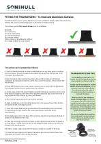
FITTING THE TRANSDUCERS - To Steel and Aluminium Surfaces The effectiveness of your system depends on correct installation. Below are the instructions for bonding the Transducer Mounting Rings to Aluminium or Steel surfaces. The surface must be flat, smooth & clean prior to installation. Do not fit: On a weld seam. On top of weld spatter On a concave surface On a convex surface Within 150mm of a bulkhead or stiffener On a rough, oxidised or rusty surface The surface can be prepared as follows: 1. Once the desired location has been established remove any loose paint or coatings from the surface....
Open the catalog to page 8
FITTING SONIHULL - To GRP/ FRP Surfaces The effectiveness of your system depends on correct installation. Below are the instructions for bonding the Transducer Mounting Rings to GRP (Glass Reinforced Plastic (or ‘fibreglass’) and FRP (Fibre Reinforced Plastic, like Carbon-fibre, Kevlar structures). The surface must be flat, smooth & clean prior to installation. Do not fit: If there is any damage or delamination below the transducer. On a convex surface. On a concave surface. Within 150mm of a bulkhead or stiffener On a rough or uneven surface On a wooden or ply-wood structure – wood insulates...
Open the catalog to page 9
FITTING THE TRANSDUCERS - In ‘Foam Core’ or ‘Sandwich’ FRP GRP Constructions DANGER – Consult a qualified marine technician with GRP/FRP expertise before fitting Sonihull to Foam Core or ‘Sandwich’ structures. DO NOT FIT TRANSDUCERS TO THE INNER LAYER OF THE SANDWICH CONSTRUCTION The foam core will dampen the Ultrasound signal and the wetted surface will not be protected from bio-fouling. The transducer must have a clear line of transmission direct to the outer layerof the sandwich. To do this, the inner layer (and some of the core material below) must be removed. Once the outer layer of the...
Open the catalog to page 10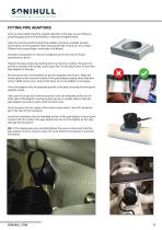
FITTING PIPE ADAPTORS Once you have determined the outside diameter of the pipe you are fitting to, protecting pipework from biofouling is relatively straightforward. Take the correctly-sized Sonihull Pipe Adaptor and find a suitable location for bonding it to the pipework that’s being protected. Ensure you are at least 250mm from a pipe flange, valve-body or bulkhead. Consider accessibility for ease of installation and in the event of future maintenance checks. Prepare the pipe surface by sanding down any exterior coating. The goal is to provide a smooth, solid surface and a good ‘key’ for the...
Open the catalog to page 11All Sonihull catalogs and brochures
 Sonihull 4 Installation Manual
13 Pages
 Sonihull ECO Brochure
6 Pages
 Sonihull 8 Installation Manual
13 Pages

