- Catalogs
- sm electrics
- Engine Order Telegraph System (EOT)
- Products
- Catalogs
- News & Trends
- Exhibitions
Engine Order Telegraph System (EOT)
1 /1Page

Engine Order Telegraph System (EOT)
1 /1Page
Catalog excerpts

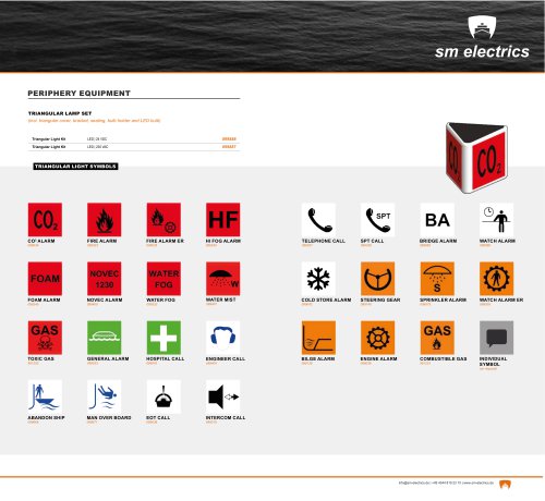
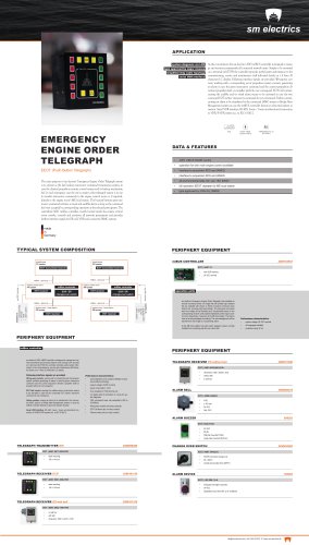
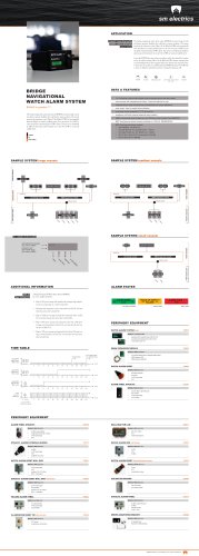
APPLICATION system diagnosis via LCD type approved by all major classes serial VDR interface The main purpose of sm electrics‘ Engine Order Telegraph system is to generate the desired RPM or pitch value for the connected propulsion remote control system by a sustained and reliable lever – known as well as human machine interface (HMI). In case the connected propulsion remote control system is disturbed the engine order telegraph system is in use to transfer manoeuvre commands to the engine control room or, if required, directly to the engine room‘s ME local station. The given manoevre command activates an audible alarm as long as the command has been accepted by corresponding operation at the connected participants. The modular system structure allows to extend the system by wing control units. All telegraphs located on the bridge e.g. bridge FWD, bridge AFT, wing SB, wing PS are connected to each other by a virtual mechanical shaft to make them work synchronously. That virtual shaft is called Electrical Shaft and oprerates as a remote control of the main bridge FWD telegraph which is providing the main interface to the connected propulsion remote control system. The centralized A067 mt-Bus controller, mostly located inside the engine control room console, controls and monitors all network participants and provides further interface signals for ER call, VDR and connected IAMC systems. ENGINE ORDER TELEGRAPH system voltage: sm electrics‘ Engine Order Telegraph (EOT) formerly designed and distributed by Stein Sohn respectively Interschalt represent the embodiment of safe and sustained µP controlled human machine interface as a basic part of the connected remote propulsion system. DATA & FEATURES Type approved by major classification societies the equipment is available for various control application. The highly integrated system is administrating a single interface to the potential propulsion system by high-precision shock resistant potentiometer, contact-free optical current transmitter or other defined physical interface unit. The well established µP controlled “Electrical Shaft” allows a secure Bridge FWD EOT’s remote control by corresponding lever controller located typically on the Bridge Wings and/or Bridge AFT. TYPICAL SYSTEM COMPOSITION PERIPHERY EQUIPMENT DOUBLE EOT BRIDGE LEVER engine control room mtBus controller mtBUS CONTROLLER interface to • • ER Call • • alarm system engine room - local station CHANGE OVER SWITCH PERIPHERY EQUIPMENT SMALL CONTROL LEVER DOUBLE CONTROL LEVER FOR WING CONSOLE EOT/EEOT RECEIVER ER with wall box EOT RECEIVER ER with wall box
Open the catalog to page 1All Sm electrics catalogs and brochures
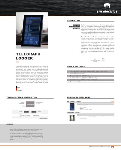 Telegraph Logger
1 Page
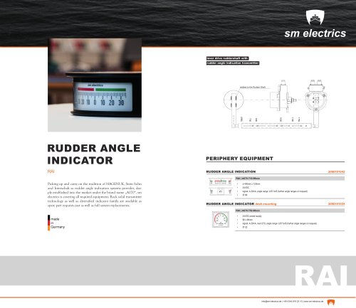 RAI
RAI1 Page
 HOCS
HOCS1 Page
 LIAS
LIAS1 Page
 BNWAS
BNWAS1 Page
 LSAS
LSAS1 Page
 Product catalog
33 Pages