- Catalogs
- sm electrics
- Emergency Engine Order Telegraph System (EEOT)
Emergency Engine Order Telegraph System (EEOT)
1 /1Page
Emergency Engine Order Telegraph System (EEOT)
1 /1Page
Catalog excerpts

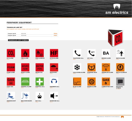
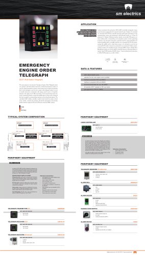
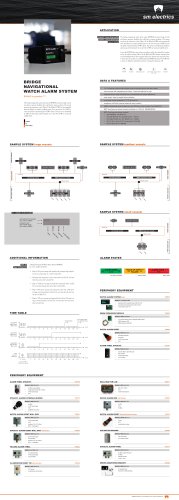
APPLICATION system diagnosis via LCD type approved by major classes As the core element, the sm electrics‘ A067 mtBUS controller is designed to manage and monitor permanently all connected network units. Simply to be mounted on a terminal rail (TS35) the controller provides useful system information to the commissioning, service and maintenance staff indicated clearly on a 4 lines 20 characters LC display. Following interface signals are provided: Wrong-way contacts, working with a correponding set of propulsion system contacts generating an alarm in case the given manoeuvre command and the current propulsion direction (propeller shaft or propeller pitch) do not correspond. EOT Call contact, causing the audible and/or visual alarm means to be activated in case the two connected EOT parties‘ manoeuvre command do not correspond. Failure contact, causing an alarm to be transferred to the connected IAMC system or Bridge Alert Management system in case the mtBUS controller detects an abnormal system situation. Serial VDR interface, RS 485, 2-wire / 3-wire uni-directional connection to VDR/S-VDR system acc. to IEC 61162-2 system voltage: EMERGENCY ENGINE ORDER TELEGRAPH DATA & FEATURES The main purpose of sm electrics‘ Emergency Engine Order Telegraph system is to operate as the last back-up manoeuvre command transmission system, in case the classical propulsion remote control system and its backup mechanism fail. In such emergency case the em‘cy engine order telegraph system is in use to transfer manoeuvre commands to the engine control room or, if required, directly to the engine room‘s ME local station. The by push buttons given manoevre command activates a visual and audible alarm as long as the command has been accepted by corresponding operation at the selected participants. The centralized A067 mt-Bus controller, mostly located inside the engine control room console, controls and monitors all network participants and provides further interface signals for ER call, VDR and connected IAMC systems. TYPICAL SYSTEM COMPOSITION wheelhouse PS system PERIPHERY EQUIPMENT mtBUS CONTROLLER engine control room PS system engine room - local station PS system operation units engine room - local station SB system mtBus controller interface to • • ER Call • • alarm system interface to • • ER Call • • alarm system engine control room SB system mtBus controller sm electrics‘ Emergency Engine Order Telegraph units installed as console mounting version on bridge with silk printed high resistant foil are available with eleven or thirten manoevre command push buttons incl. a precise night vision design. The manoevre commands sent from bridge will be indicated as a visual/audible alarm on the corresponding receiver units located traditionally at the engine control room respectively, if required, at the ME local station. The alarms have to be acknowledged accordingly. The acknowledgement will be transferred to the bridge as a responding action. Performance characteristics: system voltage: 24 VDC nominal installed into a matching wall box incl. alarm bell. PERIPHERY EQUIPMENT mtBus controller PERIPHERY EQUIPMENT - TELEGRAPH RECEIVER ER without bell Following interface signals are provided: Wrong-way contacts without bell Performance characteristics: ALARM BELL Failure contact ALARM BUZZER single hole mounted (28,5mm) CHANGE OVER SWITCH desk mounting ECR/R command change over double pole double throw (DPDT) ALARM DEVICE desk mounting triangular LED light & sounder adjustable sound level (67 up to 112dB(A)) TELEGRAPH RECEIVER ER with bell with bell
Open the catalog to page 1All Sm electrics catalogs and brochures
 Telegraph Logger
1 Page
 RAI
RAI1 Page
 HOCS
HOCS1 Page
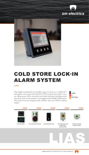 LIAS
LIAS1 Page
 BNWAS
BNWAS1 Page
 LSAS
LSAS1 Page
 Product catalog
33 Pages