- Company
- Products
- Catalogs
- News & Trends
- Exhibitions
Selector battery switch SFCBS-300-202 , SFCBS-300-402

Selector battery switch SFCBS-300-202 , SFCBS-300-402
- Continuous and intermittent ratings for DC terminal studs made of tin-plated copper, ensuring maximum conductivity and corrosion resistance.
- Models SFCBS-300-202 and SFCBS-300-402 offer different voltage and current ratings, with the former supporting 48 Volts DC and the latter 32 Volts DC.
- Both models feature a one-piece terminal stud design that prevents loosening over time and accept 3/8" (M10) ring terminals.
- Isolating cover with snap-off side pieces for protection and versatile wire access.
- IP66 rating for protection against powerful water jets.
- Compliance with UL 1500, SAE J1171, CE, RoHS, ISO 8846, and ABYC requirements for battery switches.
- Model SFCBS-300-202: 900A DC continuous, 500A DC intermittent, 300A cranking rating, 48 Volts DC.
- Model SFCBS-300-402: 900A DC continuous, 500A DC intermittent, 300A cranking rating, 32 Volts DC.
- Torque requirement of 120 in-lb (13.56 N·m) and cable size of 4/0 AWG (120 mm²).
- Surface mounting, front panel mounting, and rear panel mounting are available for both models.
- Both models meet American Boat and Yacht Council (ABYC) requirements and are designed for external ignition protection.
Catalog excerpts

www.seaflomarinerv.com Email: [email protected] www.seaflomarinerv.com Email: [email protected] Single Circuit ON/OFF Battery Disconnect Switch 4 Position Mini Selector Battery Switch • Switches a single battery to a single load group • Tin-plated copper studs for maximum conductivity and corrosion resistance • Studs accept 3/8" (M10) ring terminals • One-piece terminal stud design never loosens over time • Isolating cover with three snap-off side pieces protects rear contacts and allows wire access in any direction • Switches an isolated battery bank to all loads or combines battery banks to all loads • Tin-plated copper studs for maximum conductivity and corrosion resistance • Studs accept 3/8" (M10) ring terminals • One-piece terminal stud design never loosens over time • Isolating cover with three snap-off side pieces protects rear contacts and allows wire access in any direction Switch Mounting Options Regulatory • CE, RoHS, ISO 8846 • Meets all American Boat and Yacht Council (ABYC) requirements for battery switches • Meets UL 1500 and SAE J1171 external ignition protection requirements • IP66 – protected against powerful water jets Rear panel mounting Front panel mounting Regulatory • CE, RoHS, ISO 8846 • Meets all American Boat and Yacht Council (ABYC) requirements for battery switches • Meets UL 1500 and SAE J1171 external ignition protection requirements • IP66 – protected against powerful water jets Surface mounting Surface mounting Front panel mounting Starter or other load Rear panel mounting Switch Mounting Options Starter or other load Specifications Model Continuous Rating Continuous Rating DC Terminal Stud, Tin-Plated Copper DC Terminal Stud, Tin-Plated Copper Torque 120 in-lb (13.56 N·m) Cable Size to Meet Ratings* Torque 120 in-lb (13.56 N·m) Cable Size to Meet Ratings* Maximum Voltage Rating Maximum Voltage Rating Insulating cover removal Cover breakout diagram Apply steady pressure inwards 1or2or1+2 Switch Mounting OptionsSurface mountingFront panel mounting and Rear panel mounting Switch Mounting OptionsSurface mounti
Open the catalog to page 1All SEAFLO catalogs and brochures
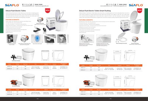 Yacht toilet SFMTE1-05
1 Page
 Boat pump SFCPA series
1 Page
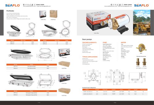
 Boat pump SFGP series
1 Page
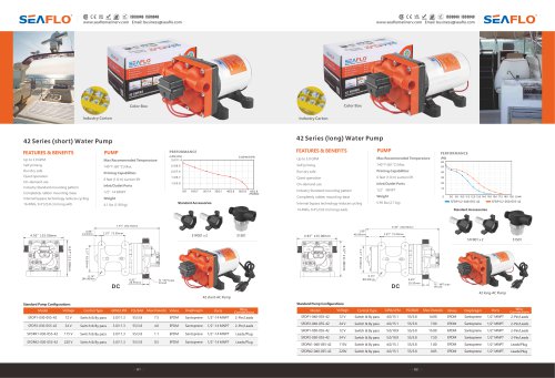 BOAT PUMP 42 SERIES
1 Page
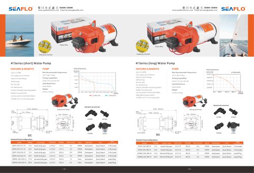 BOAT PUMP 41 SERIES
1 Page
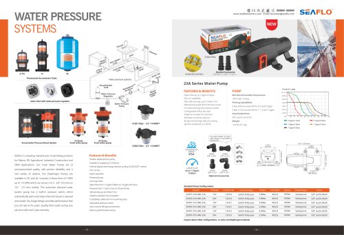 BOAT PUMP 23A SERIES
1 Page
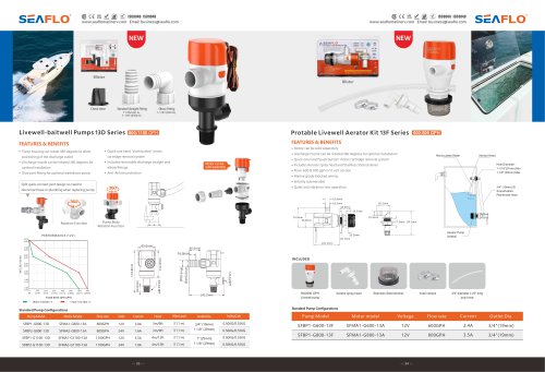 BOAT PUMP 13D SERIES
1 Page
 BOAT PUMP 11 SERIES
1 Page
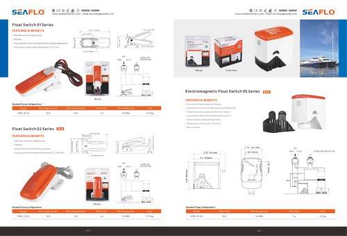
 BOAT PUMP 01 SERIES
1 Page
 BOAT PUMP 14A SERIES
1 Page


- SEAFLO boat pump
- SEAFLO LED light
- SEAFLO boat light
- SEAFLO navigation light
- SEAFLO transfer pump
- SEAFLO LED navigation light
- Cleat
- LED spotlight
- SEAFLO boat navigation light
- LED light strip
- Boat light strip
- Boat spotlight
- Interior light strip
- Cabin light strip
- SEAFLO black navigation light
- SEAFLO 12 V pump
- SEAFLO white navigation light
- SEAFLO impeller pump
- SEAFLO ship floodlight
- SEAFLO metal navigation light