- Catalogs
- R&D Marine
- Flexible Shaft Couplings
Flexible Shaft Couplings

Flexible Shaft Couplings
- Ensure connectors are clean.
- Remove bolts and strap to access the coupling hole.
- Insert the rolled earthing connector.
- Reattach strap and bolts without damaging the connector.
- Install the coupling as instructed.
- Check electrical continuity upon installation and every 3-6 months.
- Various part numbers and sizes are listed for specific coupling models.
- Align engine and stern gear without the flexible coupling.
- Bolt the coupling between rigid couplings.
- Check alignment with feeler gauges at 90° intervals.
- Ensure consistent gap for accurate alignment.
- Recommended gap difference: 0.25 mm / 0.010 inch.
- Run installation to working temperature and re-check torque settings.
- Recommended tightening torques are provided for various bolt sizes.
Catalog excerpts
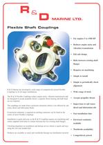
Flexible Shaft: Couplings R&D Marine has developed a wide range of competitively priced Flexible Couplings to fit all major installations. The R&D Flexible Couplings reduce engine noise, vibration transmission and are designed to accept propeller thrust, a separate thrust bearing and bulk head The couplings are made from a polyester elastomer which is not affected by salt water, diesel and lubrication fluids. If electrical continuity is required an earthing connector can be fitted in the centre of most Flexible Couplings. Installation is quick and easy as the R & D Coupling requires no machining and comes supplied with bolts to connect between the two existing shaft flanges. Checking alignment on installation and during service checks is quick and easy using the red cone headed bolt. Products are available ex-stock and worldwide through our distribution network. Reduces engine noise and vibration transmission Fail safe design Bolts between existing shaft Simple to periodically check Wide range of stock Accepts propeller thrust Impervious to salt water, diesel and lubrication oils Fast installation time Electrical continuity Worldwide availability Competitively priced
Open the catalog to page 1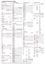
Coupling Selection Guide BORG WARNER ENFIELD and SONIC DRIVES S= Shallow Case, D= Deep Case SELF CHANGE GEARS TWIN DISC SC= Shallow Case, DC= Deep Case TWIN DISC cont'd 6" Flange 13.2 mm bolt holes 910-003, 6" Flange 16.3mm bolt holes 910-006, Couplings 910-030, 910-035, 910-041 and 910-045 will require suitable adaptors for the gearbox flange
Open the catalog to page 3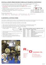
INSTALLATION PROCEDURE FOR R&D MARINE COUPLINGS 1. Roughly align engine and stern gear without flexible coupling i.e. only two rigid half couplings pushed together. 2. Bolt "R & D Marine" coupling between the two rigid couplings. Tightening details as below. 3. Check alignment of engine by placing feeler gauges between the RED CONE HEADED BOLT and the rigid half coupling. Repeat for the SAME bolt at 90° intervals by 4. If the gap is the same in all four positions, the engine is accurately aligned. Recommended minimum to maximum gap difference: 0.25 mm / 0.010 inch. 5. Run installation to bring...
Open the catalog to page 4All R&D Marine catalogs and brochures
 Rope Cutter
2 Pages
 Steel Clamp Half Couplings
4 Pages
 Damper Drive Plates
4 Pages
 Flexible Engine Mountings
4 Pages