
- Catalogs
- Quantum Marine Engineering
- ML 400-AS

- Products
- Catalogs
- News & Trends
- Exhibitions
ML 400-AS

ML 400-AS
The ML400-AS Rotor Stabilizer Hull Unit is designed for vessels with a typical length of 45-70m and an operating speed range of 2-16 knots. The rotor dimensions are 460mm x 3220mm, with an overall weight of 5500kg. The unit is compact, with a length of 2443mm, width of 1350mm, and height of 1273mm.
Installation and Operation:
The stabilizer unit is delivered fully assembled, requiring minimal disassembly for installation. It does not require a customized hull pocket, simplifying the installation process. The unit provides smooth power transfer via precision roller bearings and allows for precise control of lift force by varying the RPM and direction of the rotor.
Efficiency and Safety:
The ML400 offers exceptional hydrodynamic efficiency when properly sized and operated within acceptable speeds. It features an automatic retract mechanism for safety, allowing the rotor to stow swiftly in case of impact. The design includes a breakaway feature to preserve hull integrity during severe impacts.
Performance:
The ML400 is designed to maximize energy transfer using the Magnus Effect, suitable for demanding military and commercial applications. It provides significant roll reduction at loitering speeds and minimizes drag when not in use. The rotor can be stowed parallel to the hull to reduce drag.
Comparison with Fin Stabilizers:
The ML400 rotor offers advantages over fin stabilizers, as it can be placed in a larger longitudinal region on the hull without affecting steering or experiencing excessive pitching forces. At lower speeds, rotors are deployed for optimal performance, and as speed increases, they swing aft to reduce drag.
Warranty and Support:
The equipment is covered by a one-year comprehensive warranty, with service and technical support available worldwide.
Conclusion:
The ML400 Series hull unit is a high-performance stabilizer system designed with the latest technology and materials, offering superior roll reduction and efficiency for vessels operating at various speeds.
Catalog excerpts
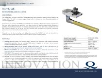
TECHNICAL SPECIFICATION DOCUMENT ROTOR STABILIZER HULL UNIT DESCRIPTION: The ML400 Series hull unit is designed to provide maximum energy transfer in terms of lift force based on the Magnus Effect. The unit is a compact rugged design built to withstand the most demanding military and commercial applications. For maximum roll reduction, the ML400 is mounted in the turn of the bilge with the rotor oriented perpendicular to the vessel hull during underway operations. Rotor spin direction and speed are altered during operation, as needed, to obtain optimal performance. To minimize appendage drag, the rotor stows neatly, parallel to the vessel hull, when the stabilizers are not in use. The rotor orientation and spin functions are precisely managed by Quantum’s hydraulic and electrical control systems. Designed using the latest technology and high-quality materials the ML400 Series hull unit offers the best performance of any system where significant roll reduction is required at loitering speeds. FEATURES: SIMPLE INSTALLATION: The stabilizer unit is delivered fully assembled with minimal disassembly required for installation. Since no customized hull pocket is required for the rotor’s stowed position, complicated hull shape fabrication is avoided. SMOOTH OPERATION: The unit provides smooth power transfer from the rotor to the ship’s hull via precision roller bearings used in both the spin drive shaft and the main shaft. PRECISION CONTROL: By varying the RPM and direction of rotation of the tube, the lift force can be controlled with razor sharp precision, resulting in instantaneous response. EFFICIENCY: When properly sized and operating within acceptable vessel speeds, rotary stabilizers provide exceptional hydrodynamic efficiency compared with other stabilizer systems available. SAFETY: The rotor’s hydraulic system is equipped with automatic retract mechanism to allow the rotor to swiftly stow in case of impact during operation. While not in operation, the rotor is elegantly stowed along the hull, where it offers minimal possibility of impact and minimal effect during maneuvering conditions. In case of severe impact, half of the rotor tube will break away, in a design feature intended to sacrifice the rotor unit in order to preserve hull integrity. Typical Vessel Length* Operating Speed Range Rotor Dimensions Length (inside vessel after installation)** Width** Height (overall)** Weight (dry) *Provided for reference only. Consult a Quantum representative for system sizing. ** Dimensions are of the equipment, and do not include service allowances. All information contained within this document remains the absolute property of the Quantum Group and is subject to change at any time. Any use of the information for other than the intended purpose is expressly forbidden. Consult a Quantum representative for more information. INNOVATION Equipment is covered by Quantum’s 1 year comprehensive warranty. Service and technical support are available worldwide.
Open the catalog to page 1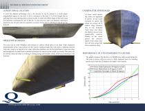
TECHNICAL SPECIFICATION DOCUMENT LONGITUDINAL LOCATION A rotor has distinct advantages over a fin because it can be placed in a much larger longitudinal region on the hull. A fin is restricted to the mid 1/3 of hull length due to pitching forces and steering effects, however this is where the fullest shape of the hull exists and therefore restricting the size of the fin. A rotor however does not influence steering if placed too far aft and will not experience excessive forces due to pitching if placed too far forward. OPERATION SUMMARY The rotor has an outer fiberglass tube (shown in yellow)...
Open the catalog to page 2All Quantum Marine Engineering catalogs and brochures
 QC2600 XT™
1 Page
 QC3600 XT™
1 Page
 QuantumControl ARC3001
1 Page
 QuantumControl SMC4000
1 Page
 QuantumFinP-QC1800.pdf
1 Page
 QuantumControl ARC3010
1 Page
 QuantumSteering BR270
1 Page
 Quantum HPU QP7575
1 Page
 Quantum HPU QRS15
1 Page
 Quantum HPU QRS20
1 Page
 Quantum HPU QRT15
1 Page
 Quantum HPU QRT35
1 Page
 HPU QRT35
1 Page
 HPU QRT15
1 Page
 HPU QRS20
1 Page
 HPU QRS15
1 Page
 Quantum HPU XT Type2
1 Page
 QC2400
1 Page
 QC2200
1 Page
 QC1500
1 Page
 ML 220
1 Page
 ML 400-AS
2 Pages
 Quantum HPU QP4040Mk1
1 Page
 Quantum HPU QP4040C
1 Page
 Quantum HPU QP3030C
1 Page
 Quantum HPU QP3030Mk3
1 Page
 Quantum HPU QP30
1 Page
 Quantum HPU QP2020
1 Page
 Quantum HPU QP20
1 Page
 Quantum HPU QP1515
1 Page
 Quantum HPU QP15
1 Page
 Quantum HPU QIS60
1 Page
 Quantum HPU QIS210
1 Page
 Quantum HPU QIS180
1 Page
 Quantum HPU QIS160
1 Page
 QuantumHPU-XT-Type2
1 Page
 QRS20
QRS201 Page
 QRT35
QRT351 Page
 QRT15
QRT151 Page
 Quantum CHP 1500-2400
1 Page
 QuantumFinP-QC3600.pdf
1 Page
 QuantumFinP-QC1000.pdf
1 Page
 QuantumXT-HullQC3600.pdf
1 Page
 QuantumXT-HullQC1800.pdf
1 Page
 QuantumXT-HullQC1200.pdf
1 Page
 QuantumHPU-XT-Type1.pdf
1 Page
 QuantumHPU-QRS15.pdf
1 Page
 QuantumThrusterQT150.pdf
1 Page
 QuantumArcher.pdf
1 Page
 QuantumMagliftML600.pdf
1 Page
 QuantumMagliftML300-AS.pdf
2 Pages
 QuantumMagliftML200-AS.pdf
2 Pages


Archived catalogs
 Quantum
6 Pages