
- Catalogs
- Progressive Automations
- PA-13 Data sheet


PA-13 Data sheet

PA-13 Data sheet
The PA-13 linear actuator operates at 12 VDC and 24 VDC with varying load capacities. It features a dynamic load capacity of up to 3000 lbs and a static load capacity of up to 2023 lbs. The actuator's speed ranges from 0.16 to 0.47 inches per second depending on the load and voltage. It includes a built-in electric shutoff and overload protection, with a duty cycle of 20% (4 minutes on, 16 minutes off). The operational temperature range is -40°C to 60°C, and it has an IP66 protection class.
Dimensions
The actuator's dimensions vary based on stroke length. For stroke lengths less than 4 inches, the dimension A is 11.87 inches, and dimension B is the stroke length plus 11.87 inches. For stroke lengths of 4 inches and greater, dimension A is the stroke length plus 7.87 inches, and dimension B is twice the stroke length plus 7.87 inches.
Speed/Current vs Load
Graphs illustrate the relationship between speed/current and load for both 12VDC and 24VDC configurations. As the load increases, the speed decreases, and the current increases.
Connectors & Feedback
The actuator uses a 2-pin connector as standard. Hall Effect equipped actuators have tinned wire leads without connectors. Feedback options include potentiometer, Hall Effect, and limit switch.
Features
The PA-13 includes a manual override feature, allowing operation under load conditions below the maximum specification. To manually override, power must be disconnected, and a hex key is used to adjust the actuator.
Catalog excerpts

PA-13 Scan for more information
Open the catalog to page 1
Table of Contents Specifications Dimensions Speed/Current vs Load Connectors & Feedback Have any queries? Our expert engineers are here to help! [email protected]
Open the catalog to page 2
Stroke Limit Switch Limit Switch Feedback Screw Type Motor Type Connector Type Wire Length Housing Material Rod Material Gear Material Color (Shaft) Color (Motor End) Noise Duty Cycle Overload Protection Operational Temperature Protection Class Feedback Options Certiffications Mounting Brackets Mounting Ends Features Speed (inch/sec) No Load Full Load 0.24 0.16 0.31 0.47 0.47 0.79" to 40" Internal - Non-Adjustable Customizable ACME Screw, Ball Screw Brushed DC Motor See Page 6 40" (customizable) 6062 Aluminum Alloy Stainless Steel Powder Metallurgy Steel Alloy Silver Graphite <90dB 20% (4 minutes...
Open the catalog to page 3
Dimensions (Dimensions in inches) For Stroke Length less than 4" For Stroke Length 12" and Greater For Stroke Length of 4" and Greater For Stroke Length greater than 24"
Open the catalog to page 4
Speed vs Load Speed vs. Load: PA-13 Linear Actuator 12VDC 1.6 1.4 Speed (inches/second) Current vs Load Current vs. Load: PA-13 Linear Actuator 12VDC 25
Open the catalog to page 5
Speed vs Load Speed vs. Load: PA-13 Linear Actuator 24VDC 1.6 1.4 Speed (inches/second) Current vs Load Current vs. Load: PA-13 Linear Actuator 24VDC 12
Open the catalog to page 6
Connectors & Feedback 2-Pin Connector (Standard) Motor Part Name Part Number Mating Part Number Tyco Electronics AMP Universal Mate-N-Lok PLUG Hall Effect Wires Hall Effect equipped actuators will come with tinned wire leads and no connector. Hall Sensor Signal 2 Leads when Extending Signal 1 Leads when Retracting Output Signal Extending Output Signal Retracting Hall Effect 1 Signal Hall Effect 2 Signal Hall Effect 1 Signal Hall Effect 2 Signal Force (lbs) Resolution (pulses/inch) Potentiometer Specifications *For Stroke Length up to 6" Signal *Actual resistance value may vary within the 0-10kΩ...
Open the catalog to page 7
Features Manual Override Operation The manual override can be carried out while the PA-13 actuator is loaded if the load experienced was below the maximum load specifications (3000lbs). To operate manual override: 1. Shut down power or disconnect the actuator from power. 2. Remove the Torx screw located in the back center of the actuator. 3. Insert a 6mm hex key into the hole. 4. Turn the hex key clockwise to retract the actuator. For extending the actuator, turn the hex key counterclockwise. 5. When finished with manual override, remove the hex key, and screw the Torx screw back in place.
Open the catalog to page 8All Progressive Automations catalogs and brochures
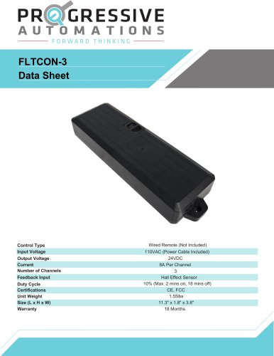 FLTCON-3
3 Pages
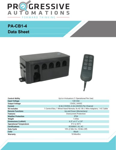 PA-CB1-4
2 Pages
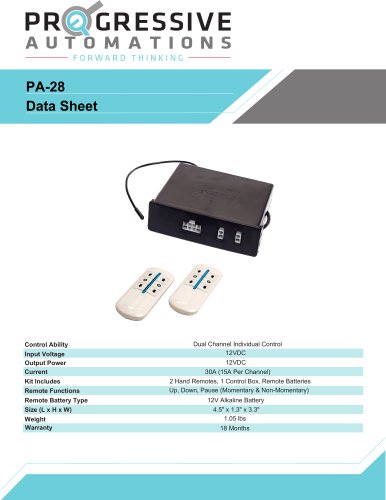 PA-28
PA-283 Pages
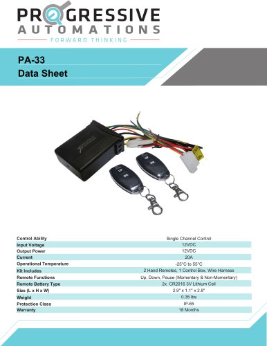 PA-33
PA-333 Pages
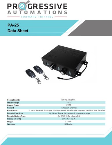 PA-25
PA-253 Pages
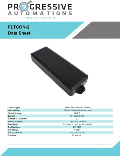 FLTCON-2
4 Pages
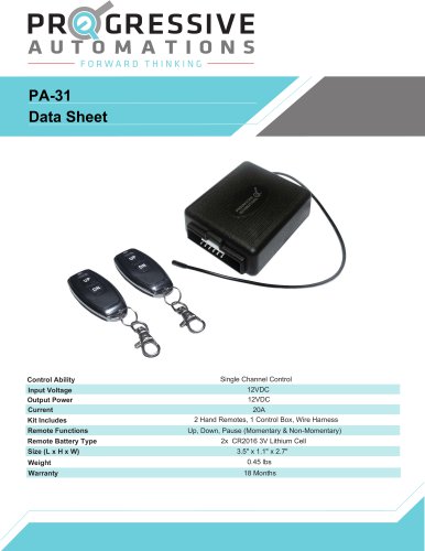 PA-31
PA-313 Pages
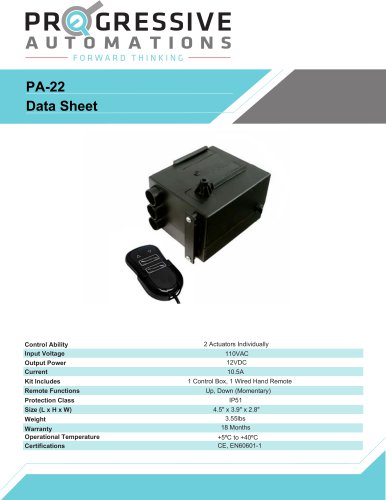 PA-22
PA-222 Pages
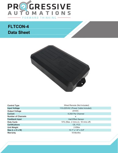 FLTCON-4
3 Pages
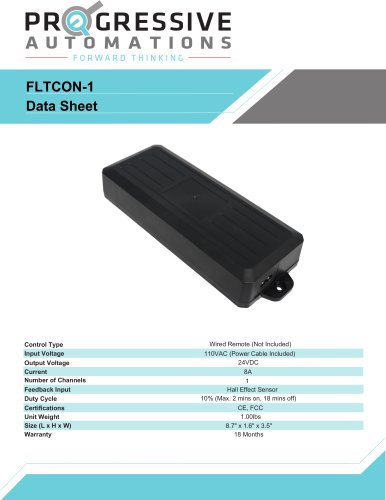 FLTCON-1
3 Pages
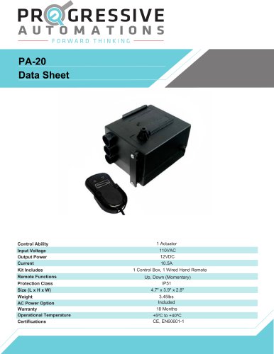 PA-20
PA-202 Pages
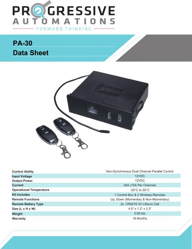 PA-30
PA-303 Pages
 PA-04 Data sheet
10 Pages
 FLT-11 Data sheet
8 Pages
 PA-01 Data sheet
7 Pages
 PA-06 Data sheet
7 Pages