
- Catalogs
- NORIS Group GmbH
- Datenblatt VFS5

- Company
- Products
- Catalogs
- News & Trends
- Exhibitions
Datenblatt VFS5

Datenblatt VFS5
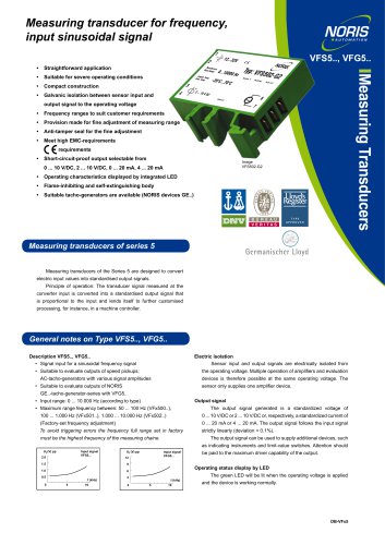
- Input Range: 0 to 10,000 Hz, with factory-set frequency adjustments for different models (VFx500, VFx501, VFx502).
- Output Signal: Standardized voltage (0-10 V/DC, 2-10 V/DC) or current (0-20 mA, 4-20 mA), with linear deviation < 0.1%.
- Operating Voltage: 9-32 V/DC, with reverse voltage protection and overvoltage tolerance.
- Temperature Range: Operating from -20°C to +70°C, storage from -45°C to +85°C.
- Protection: Galvanic isolation between sensor input and output signal, short-circuit-proof outputs.
- Compact construction with flame-inhibiting and self-extinguishing body.
- LED display for operating status.
- Anti-tamper seal for fine adjustment of measuring range.
- Compliance with high EMC requirements and various international standards (e.g., IEC, DIN).
- Input Signal: Sinusoidal, with input resistance of approx. 10 kΩ (VFS5) or 30 kΩ (VFG5).
- Reaction Time: Varies with frequency, e.g., 50 ms at 10 kHz.
- Environmental Resistance: Vibration and shock resistant, with specific standards for ESD, electromagnetic fields, and more.
Catalog excerpts

Measuring transducer for frequency, input sinusoidal signal 1 2 • Straightforward application Messbe Meas.Rangreich: e: Umgeb. Amb. Tem Temp: p: • Compact construction • Galvanic isolation between sensor input and output signal to the operating voltage Measuring Transducers • Suitable for severe operating conditions • Frequency ranges to suit customer requirements • Provision made for fine adjustment of measuring range • Anti-tamper seal for the fine adjustment • Meet high EMC-requirements • Short-circuit-proof output selectable from • Operating characteristics displayed by integrated LED • Flame-inhibiting and self-extinguishing body • Suitable tacho-generators are available (NORIS devices GE..) Measuring transducers of series 5 Measuring transducers of the Series 5 are designed to convert electric input values into standardised output signals. Principle of operation: The transducer signal measured at the converter input is converted into a standardised output signal that is proportional to the input and lends itself to further customised processing, for instance, in a machine controller. General notes on Type VFS5.., VFG5.. Description VFS5.., VFG5.. • Signal input for a sinusoidal frequency signal Electric isolation Sensor input and output signals are electrically isolated from • Suitable to evaluate outputs of speed pickups; the operating voltage. Multiple operation of amplifiers and evaluation AC-tacho-generators with various signal amplitudes devices is therefore possible at the same operating voltage. The • Suitable to evaluate outputs of NORIS sensor only supplies one amplifier device. GE..-tacho-generator-series with VFG5.. Output signal • Input range: 0 ... 10.000 Hz (according to type) • Maximum range fequency between: 50 ... 100 Hz (VFx500..), The output signal generated is a standardized voltage of 0 ... 10 V/DC or 2 ... 10 V/DC or, respectively, a standardized current of 0 ... 20 mA or 4 ... 20 mA. The output signal follows the input signal (Factory-set frequency adjustment) To avoid triggering errors the frequency full range set in factory strictly linearly (deviation < 0.1%). The output signal can be used to supply additional devices, such must be the highest frequency of the measuring chaine. as indicating instruments and limit-value switches. Attention should Input signal VFS5... be paid to the maximum driver capability of the output. Operating status display by LED The green LED will be lit when the operating voltage is applied and the dev
Open the catalog to page 1
Technical Data Series VFS5.., VFG5.. UO=9 ... 32 V/DC, UR=24 V/DC < 20% UO Integrated 2.5 times UR up to 2 ms 100% up to 10 ms Operating voltage Ripple Reverse voltage protection Overvoltage Voltage drops Power consumption Galvanic isolation Approx. 50 mA (24 V/DC) Between sensor input and output signal to the operating voltage Input signal Sinusoidal signal, NORIS tacho-generator GE Input overloading Input resistance Output VFx5..-G. 1.25 times input signal Noise voltage Error class Temperature sensitivity Voltage sensitivity Load sensitivity Reaction time Vibration resistance Shock resistance...
Open the catalog to page 2All NORIS Group GmbH catalogs and brochures
 Unique Yacht Automation
16 Pages
 Energy storage solutions
2 Pages
 Datasheet TAV131
3 Pages
 Datasheet PAx9
6 Pages
 Datasheet RG5
2 Pages
 Datasheet VFW5
2 Pages
 Datasheet RP5, RPT5
2 Pages
 Datasheet NIR3 NIQ3
20 Pages
 Datasheet VD61
6 Pages
 Datasheet FA13
14 Pages
 Datasheet NIQ31
16 Pages
 Energy Storage System
2 Pages
 NORIS Marine Overview
13 Pages
 RETROFIT - modernise your
2 Pages
 Datasheet NORISYS 4 LA4
4 Pages
 Datasheet NORISYS 4 LS4
4 Pages
 Datasheet NORISYS 4 LT4
4 Pages
 Datasheet FA54
11 Pages
 NORIS Brochure
15 Pages
 Datasheet TP31 TH31
5 Pages
 Datasheet EOT
6 Pages
 Datasheet NORISPEED FMN6
2 Pages
 Datasheet DWA
4 Pages
 Datasheet TP23
4 Pages
 Datasheet VF5
2 Pages
 Flyer NORISYS 4 CPU
2 Pages
 Datasheet RFW5
2 Pages
 NORISYS 4 - PLC Deep Sea
2 Pages
 Datasheet RTK5
2 Pages
 Datasheet RFJ5
2 Pages
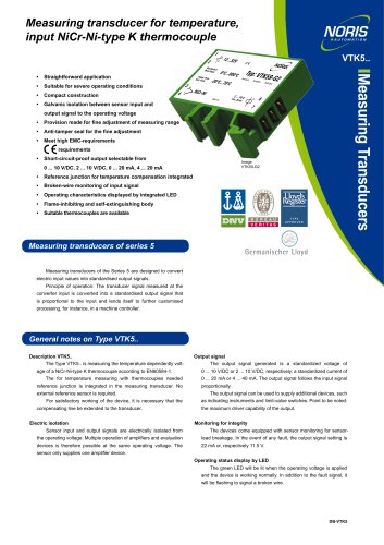 Datasheet VTK5
2 Pages
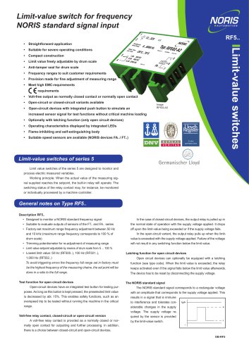 Datasheet RF5
2 Pages
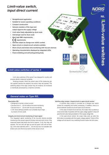 Datasheet RI5
2 Pages
 Datasheet RFG5
2 Pages
 Datasheet VPT5
2 Pages
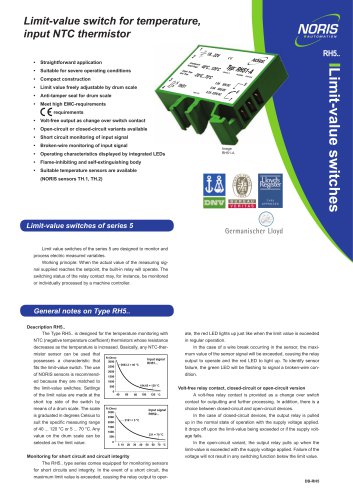 Datasheet RH5
2 Pages
 Datasheet VFS5
2 Pages
 Datasheet RH41M
2 Pages
 Datasheet RW5
2 Pages
 Datasheet VMP70
3 Pages
 Datasheet VP5
2 Pages
 Datasheet NADS3
2 Pages
 Datasheet NAD2
2 Pages
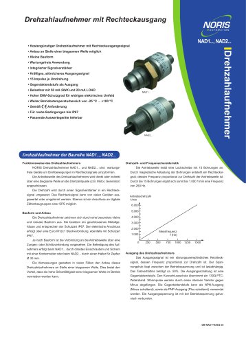 Datasheet NAD1
2 Pages
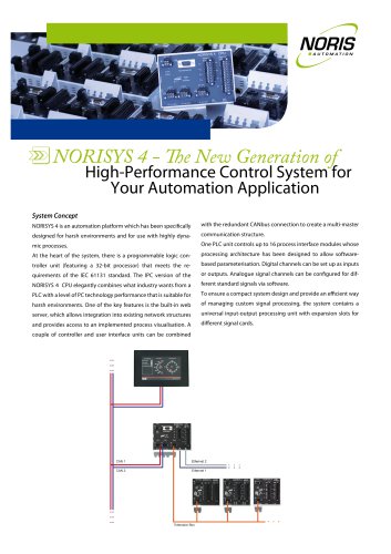 Flyer NORISYS 4
2 Pages













Archived catalogs
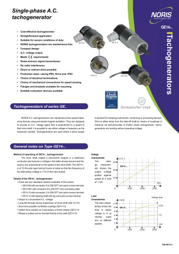 Datasheet GE14
2 Pages
 Datasheet GE12
2 Pages
- Boat sensor
- Boat indicator
- Analog indicator
- Temperature sensor
- Boat battery
- Control lever
- Boat monitoring and control panel
- Engine control lever
- Ship sensor
- Lithium battery
- Boat control lever
- Digital control lever
- Boat display
- Ship software
- Single-lever control lever
- Multi-lever control lever
- Ship control panel
- Yacht monitoring panel
- Multi-function display