- Catalogs
- NORIS Group GmbH
- Datasheet RH41M
Datasheet RH41M

Datasheet RH41M
- Supply Voltage: 18-36 VDC
- Current Consumption: Max. 10 mA
- Input Signal: Thermistor with a temperature range of 40°C to 120°C
- Output: Floating relay contact with a maximum current of 0.5 A and voltage of 60 V
- Operating Temperature: -25°C to +70°C
- Storage Temperature: -40°C to +85°C
- Vibration Resistance: Up to 4 g
- Degree of Protection: Housing IP20, connections IP00
- Line monitoring requires a transition resistor at connections 3 and 7, typically 22 kΩ, but adjustable based on system requirements.
- Bipolar wiring is used, with shielded lines recommended and a minimum distance of 0.1 m from power lines.
- Connections are made using A 6.3 x 0.8 Faston connectors.
- EMC Requirements: Meets high EMC standards with specific immunity to ESD, HF-interference, burst, surge, and conducted interference.
- Approvals: CE, GL, and BV certified.
- Use in harsh environments is supported, with a compact design for space-saving installation.
- Switching temperature is adjustable via a drum scale, with a seal feature for security.
- Short circuit and broken-wire monitoring of input signals.
- Thermoplastic housing made of Makrolon 2805.
- Reproducibility of ±0.2% and linearity of scale ±1.5%.
Catalog excerpts

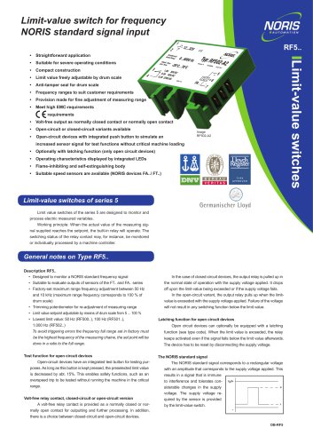
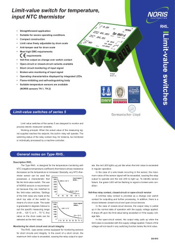
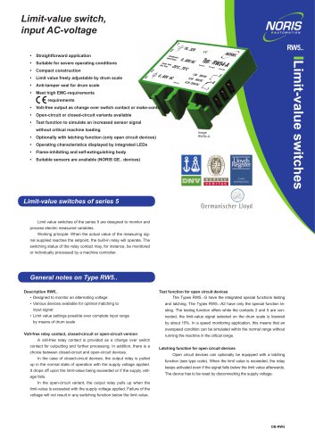
Limit-Value Switch for Temperature Thermistor Input (NTC) Easy to use Switch limit value can be adjusted using drum scale Seal feature for drum scale Meets high EMC-requirements Floating output contact Short circuit monitoring of input signal Broken-wire monitoring of input signal Thermoplastic housing (Makrolon 2805) Matching temperature sensors can be supplied Suitable for harsh operating conditions Compact design for mounting side by side Limit-Value Switch RH41M... The RH41M limit-value switch is a specially designed product for monitoring maximum temperatures in engine safety systems with a monitored open circuit arrangement. The monitored open circuit arrangement increases the availability of a system without eliminating self-monitoring of the closed circuit system in the event of a wire break and short circuit. The signal for constantly checking the functional reliability of the temperature sensor, sensor line, auxiliary voltage, relay and signal line can be evaluated separately from the temperature signal. The device is used on a TS 32 mounting rail in the same way as a snap-on terminal. It is a special type of modular terminal block with an integrated electronic measuring and switching stage. Multiple modular switching devices can be connected side by side on a rail to save space and can also be combined with modular terminal blocks. The required switching temperature can be set on a dial. The device design also envisages use in harsh/low environments in machinery applications. To enable line monitoring, the devices at connections 3 and 7 must be provided with a transition resistor. A value of 22 kΩ is quite common, but other values are possible and the resistor can also be connected by the customer. The resistance value must be based on the requirements of the monitoring system. The resistance value is identified by means of an addition to the type designation. Bipolar wiring is used between the measuring element and the switching device. With a line length of up to 20 m, the faults specified in this data sheet will not be exceeded. If greater distances need to be covered, slightly larger faults may occur that are dependent on both the line length and the selected switch point. The polarity is irrelevant when connecting the connecting line. Shielded lines must be used. A distance of at least 0.1 m is to be observed in relation to power lines. No line compensation has to be performed; no compensating line and reference point are required. All connections to the switching device must be established using A 6.3 x 0.8 Faston connectors according to DIN 46245 (AMP connectors, etc.). The Faston connectors are included in the scope of supply.
Open the catalog to page 1
Technical Data Dimensions, Connection, Diagram drum scale f Flat connector plug A6.3 x 0.8 DIN 46244 with insulating sleeve in accessories kit Capstan head screw —i according to DIN 404 Switching state Connection Signal at output 4/6 (Contact position and internal resistance,,R" with various operating states) Deliverable versions and ordering information Type 11 Transition resistor R specified and connected by user. NORIS Automation GmbH | Muggenhofer Strasse 95 | 90429 Nuremberg | Germany | Phone: +49 911 3201-220 | Fax: +49 911 3201-150 | [email protected] | www.noris-group.com valid from...
Open the catalog to page 2All NORIS Group GmbH catalogs and brochures
 Unique Yacht Automation
16 Pages
 Energy storage solutions
2 Pages
 Datasheet TAV131
3 Pages
 Datenblatt VFS5
2 Pages
 Datasheet PAx9
6 Pages
 Datasheet RG5
2 Pages
 Datasheet VFW5
2 Pages
 Datasheet RP5, RPT5
2 Pages
 Datasheet NIR3 NIQ3
20 Pages
 Datasheet VD61
6 Pages
 Datasheet FA13
14 Pages
 Datasheet NIQ31
16 Pages
 Energy Storage System
2 Pages
 NORIS Marine Overview
13 Pages
 RETROFIT - modernise your
2 Pages
 Datasheet NORISYS 4 LA4
4 Pages
 Datasheet NORISYS 4 LS4
4 Pages
 Datasheet NORISYS 4 LT4
4 Pages
 Datasheet FA54
11 Pages
 NORIS Brochure
15 Pages
 Datasheet TP31 TH31
5 Pages
 Datasheet EOT
6 Pages
 Datasheet NORISPEED FMN6
2 Pages
 Datasheet DWA
4 Pages
 Datasheet TP23
4 Pages
 Datasheet VF5
2 Pages
 Flyer NORISYS 4 CPU
2 Pages
 Datasheet RFW5
2 Pages
 NORISYS 4 - PLC Deep Sea
2 Pages
 Datasheet RTK5
2 Pages
 Datasheet RFJ5
2 Pages
 Datasheet VTK5
2 Pages
 Datasheet RF5
2 Pages
 Datasheet RI5
2 Pages
 Datasheet RFG5
2 Pages
 Datasheet VPT5
2 Pages
 Datasheet RH5
2 Pages
 Datasheet VFS5
2 Pages
 Datasheet RW5
2 Pages
 Datasheet VMP70
3 Pages
 Datasheet VP5
2 Pages
 Datasheet NADS3
2 Pages
 Datasheet NAD2
2 Pages
 Datasheet NAD1
2 Pages
 Flyer NORISYS 4
2 Pages


Archived catalogs
 Datasheet GE14
2 Pages
 Datasheet GE12
2 Pages
- Boat sensor
- Boat indicator
- Analog indicator
- Boat battery
- Control lever
- Boat monitoring and control panel
- Engine control lever
- Ship sensor
- Boat control lever
- Lithium battery
- Nautical display
- Digital control lever
- Boat display
- Ship software
- Multi-lever control lever
- Single-lever control lever
- Ship control panel
- Multi-function display
- Yacht monitoring panel