- Catalogs
- NORIS Group GmbH
- Datasheet RFW5
Datasheet RFW5

Datasheet RFW5
Catalog excerpts

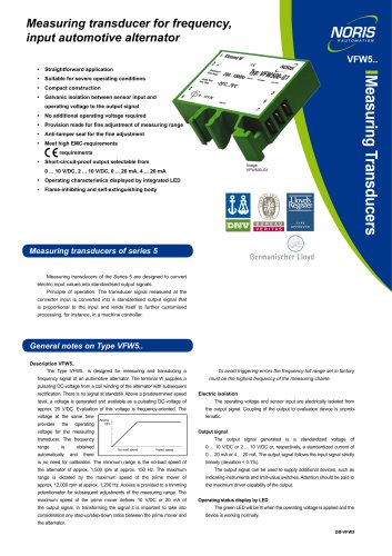
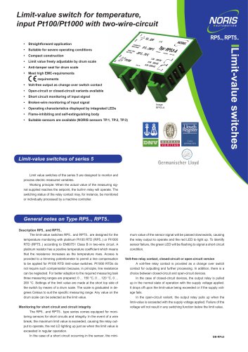
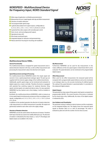
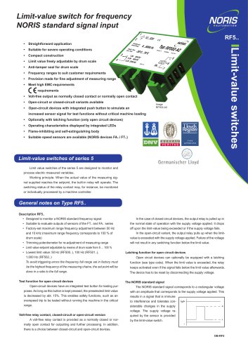
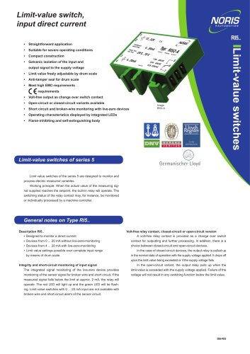
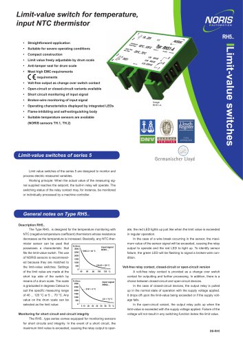
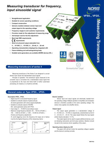
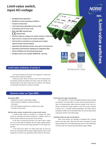
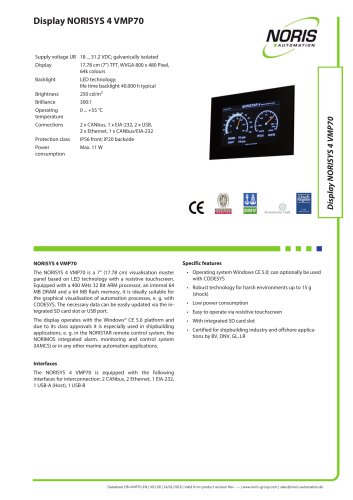
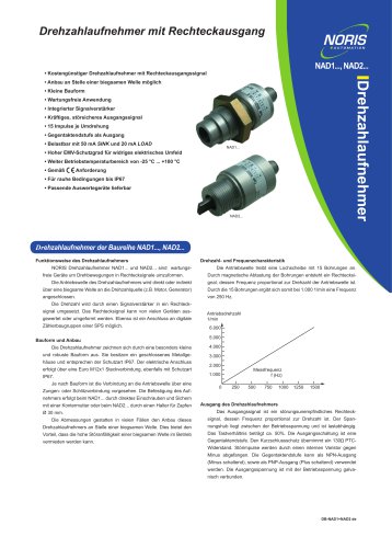
Limit-value switch for frequency, input automotive alternator 1 2 • Straightforward application • Compact construction • No additional supply voltage required • Limit value freely adjustable by drum scale Limit-value switches • Suitable for severe operating conditions • Anti-tamper seal for drum scale • Provision made for fine adjustment of measuring range • Meet high EMC-requirements • Volt-free output as normally closed contact or normally open contact • Open-circuit or closed-circuit variants available • Open-circuit devices with integrated push button to simulate an increased sensor signal for test functions without critical machine loading • Optionally with latching function (only open circuit devices) • Operating characteristics displayed by integrated LEDs • Flame-inhibiting and self-extinguishing body Limit-value switches of series 5 Limit value switches of the series 5 are designed to monitor and process electric measured variables. Working principle: When the actual value of the measuring signal supplied reaches the setpoint, the built-in relay will operate. The switching status of the relay contact may, for instance, be monitored or individually processed by a machine controller. General notes on Type RFW5.. Description RFW5.. The Type RFW5.. is designed for monitoring a frequency signal of an automotive alternator. The terminal W supplies a pulsating DC-voltage from Test function for open circuit devices a coil winding of the alternator with subsequent rectification. There is no sig- Open-circuit devices have an integrated test button. As long as this nal at standstill. Above a predetermined speed level, a voltage is generated button is kept pressed, the preselected limit value is decreased by approx. and available as a pulsating DC-voltage of approx. 26 V/DC. Evaluation of 15%. This enables safety functions, such as an overspeed trip to be tested this voltage is frequency-oriented. The voltage at the same time provides without running the machine in the critical range. the supply voltage for the limit-value switch. The frequency range Volt-free relay contact, closed-circuit or open-circuit version A volt-free relay contact is provided as a normally closed or normally open contact for outputting and further processing. In addition, there is a cally and there is no need for calibration. The minimum range choice between closed-circuit and open-circuit devices. No-load speed Rated speed is the no-load speed of the alternator of approx. 1,500 rpm at approx. 150 In the case of closed-circuit devices, the output relay is pulled up in the normal state of operation with the supply voltage applied. It drops off upon the limit-value being exceeded or if the supply voltage fails. Hz. The maximum range is dictated by the maximum speed of the prime In the open-circuit variant, the output relay pulls up when the limit-value mover of approx. 12,000 rpm at approx. 1,200 Hz. Access is provided to is exceeded with the supply voltage applied. Failure of the voltage will not a trimming potentiometer for subsequent adjustments of the measuring result in any switching function below the limit value. range. Settings of the limit value are made at the short top side of the device by means of a drum scale graduated in per cent. The maximum speed Latching function for open circuit devices of the prime mover defines 100%. Settings can be at any value between Open circuit devices can optionally be equipped with a latching 20 - 100%. In selecting the limit value it is important to take into considera- function (see type code). When the limit value is exceeded, the relay tion any step-up/step-down ratios between the prime mover and the alternator. No switching functions are provided below the no-load speed. To avoid triggering errors the frequency full range set in factory must keeps activated even if the signal falls below the limit value afterwards. The device has to be reset by disconnecting the supply voltage. be the highest frequency of the measuring chaine, the set point will be done in a ratio
Open the catalog to page 1
Other Data Technical Data Series RFW5.. Device codes R [Limit-value switch Input signal FW [Frequency input for a terminal W of a 24 V automotive alternator Type series 5 Type 5 Input range Relay position NORIS Automation GmbH Muggenhofer Strasse 95 90429 Nuremberg Germany Version 01.05: 07/2014 Changes reserve
Open the catalog to page 2All NORIS Group GmbH catalogs and brochures
 Unique Yacht Automation
16 Pages
 Energy storage solutions
2 Pages
 Datasheet TAV131
3 Pages
 Datenblatt VFS5
2 Pages
 Datasheet PAx9
6 Pages
 Datasheet RG5
2 Pages
 Datasheet VFW5
2 Pages
 Datasheet RP5, RPT5
2 Pages
 Datasheet NIR3 NIQ3
20 Pages
 Datasheet VD61
6 Pages
 Datasheet FA13
14 Pages
 Datasheet NIQ31
16 Pages
 Energy Storage System
2 Pages
 NORIS Marine Overview
13 Pages
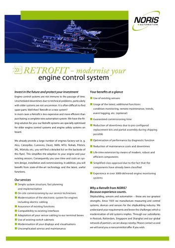 RETROFIT - modernise your
2 Pages
 Datasheet NORISYS 4 LA4
4 Pages
 Datasheet NORISYS 4 LS4
4 Pages
 Datasheet NORISYS 4 LT4
4 Pages
 Datasheet FA54
11 Pages
 NORIS Brochure
15 Pages
 Datasheet TP31 TH31
5 Pages
 Datasheet EOT
6 Pages
 Datasheet NORISPEED FMN6
2 Pages
 Datasheet DWA
4 Pages
 Datasheet TP23
4 Pages
 Datasheet VF5
2 Pages
 Flyer NORISYS 4 CPU
2 Pages
 NORISYS 4 - PLC Deep Sea
2 Pages
 Datasheet RTK5
2 Pages
 Datasheet RFJ5
2 Pages
 Datasheet VTK5
2 Pages
 Datasheet RF5
2 Pages
 Datasheet RI5
2 Pages
 Datasheet RFG5
2 Pages
 Datasheet VPT5
2 Pages
 Datasheet RH5
2 Pages
 Datasheet VFS5
2 Pages
 Datasheet RH41M
2 Pages
 Datasheet RW5
2 Pages
 Datasheet VMP70
3 Pages
 Datasheet VP5
2 Pages
 Datasheet NADS3
2 Pages
 Datasheet NAD2
2 Pages
 Datasheet NAD1
2 Pages
 Flyer NORISYS 4
2 Pages


Archived catalogs
 Datasheet GE14
2 Pages
 Datasheet GE12
2 Pages
- Boat sensor
- Boat indicator
- Analog indicator
- Temperature sensor
- Boat battery
- Control lever
- Boat monitoring and control panel
- Engine control lever
- Ship sensor
- Boat control lever
- Lithium battery
- Nautical display
- Digital control lever
- Boat display
- Ship software
- Multi-lever control lever
- Single-lever control lever
- Ship control panel
- Multi-function display
- Yacht monitoring panel