- Catalogs
- NORIS Group GmbH
- Datasheet NIQ31
Datasheet NIQ31

Datasheet NIQ31
Catalog excerpts

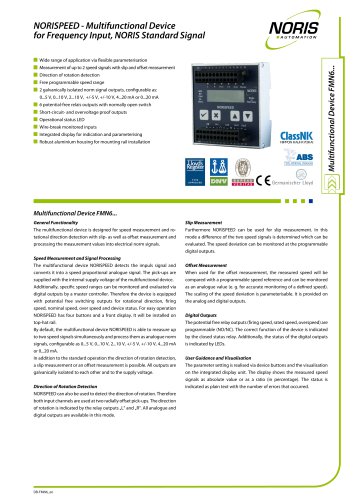
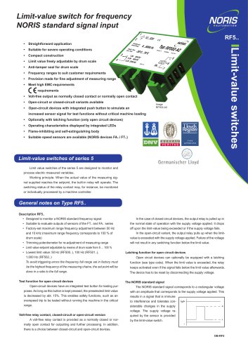
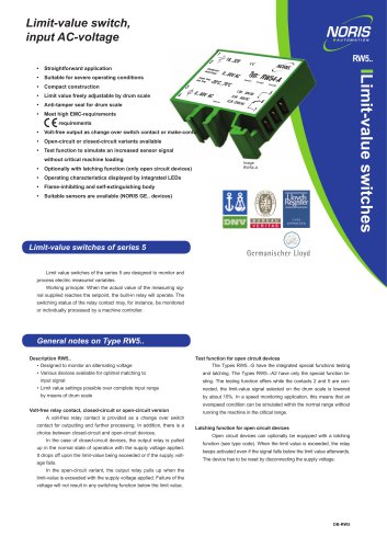
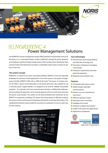
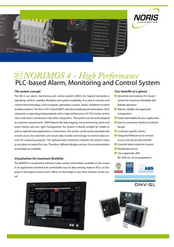
Type NORIMETER 3 analogue indicator 360° indicator with stepper motor technology universally applicable Construction type Square type NIQ31 Stepper motor principle Housing sizes Protection class IEC 60529: Front of housing IP66, IP67 and IP68 (1 m, 24 h); rear of housing IP30 (standard, higher on request) Measured variables Analogue measurement signals (current/ voltage); frequency signals, resistive sensor signals (Pt100/Pt1000, NTC thermistor, resistance) Scale angular Housing material Glas fibre reinforced and uv stabilised plastic; upper part: PC GF10; base plate: PC GF30; face made of lumenized float glass Externally dimmable LED illumination Supply voltage 18 ... 36 VDC, other voltages on request Fire protection Display principle Special features Type NIQ31 analogue indicators are commonly used in the fields of the Shipbuilding industry, e,g, to indicate the rudder position, propeller position and pitch on ships. Signals commonly used in industry, such as analogue measuring signals, are fed in directly and shown on a customised scale with a dial that can be turned through 360°. Thanks to its mechanical design, the casing is extremely resistant to salt spray, enabling use in outdoor applications. The DIN-compliant housing sizes are suitable for installation in control cabinets and control panels with pre-stamped standardised installation openings. • Long lifetime due to compact and robust technology, a high protection class and a glass-fibre-reinforced, salt spray resistant plastic housing, suitable for outdoor areas Display principle • Option: Motor with anti-clockwise rotation • Individual scale design and corporate logos possible, even for small quantities • Monitoring for valid measuring signal • Option: Minimum-Maximum value indication for saving and indicating the highest and lowest measured value • Fulfils all conventional ship classifications A high resolution motor without a mechanical stop is used in 360° indicators to enable continuous rotation of the dial. The entire measuring range is divided into 4320 graduations. As the motor in this indicator has no mechanical stop, the zero point is found by scanning of a position marker on the underside of the dial. Gear backlash of the stepper motor is virtually eliminated by a special motor controller. This method enables pinpoint positioning accuracy of the dial in both directions. The indicator additionally corrects the gear backlash every second when the dial is stationary. The reading is corrected if it deviates from the correct value (within the gear backlash) due to impact or vibration. Datasheet DB-NIQ31-EN | V01.06 | 07/05/2021 | Valid from product revision A | www.noris-group.com | sales@n
Open the catalog to page 1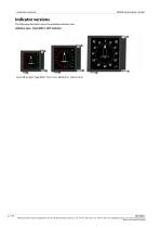
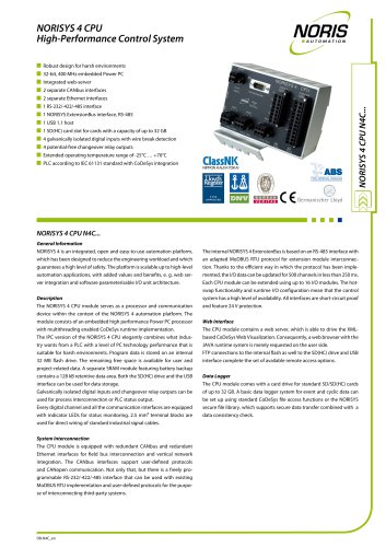
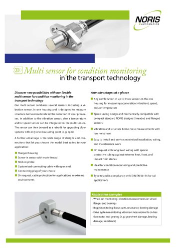
NORIS Automation GmbH Indicator versions The following illustration show the available indicator sizes Indicator sizes - Type NIQ31, 360° indicator From left to right: Type NIQ31 72x72 mm, 96x96 mm, 144x144 mm NORIS Automation GmbH | Muggenhofer Str. 95 | 90429 Nuremberg | Germany | Tel: +49 911 3201-220 | Fax: +49 911 3201-150 | [email protected] | www.noris-group.com Errors and omissions excepted
Open the catalog to page 2
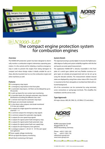
NORIS Automation GmbH Standard version Scale and dial The scale is marked and graduated according to customer requirements. Scale and dial (black) Standard version Graduations and dial markings Customised versions Left red, right green Available in all RAL colours in accordance with customer requirements, own logos possible Orientation graduation or any other scale graduations available according to customer requirements Scale illumination and dial illumination effects Without illumination: white graduations and scale markings; with illumination: graduations and scale markings red, green or in...
Open the catalog to page 3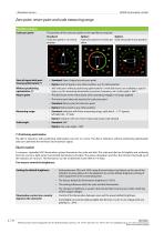
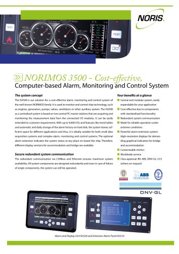
NORIS Automation GmbH Zero point, return point and scale measuring range Possible versions Scale zero point The position of the scale zero point can be specified as required. Standard: Scale zero point in 12 o'clock position Option: Option: Scale zero point in 6 o'clock po- Scale zero point in any position sition Start of signal with positioning optimisation (*) • Standard: Start of signal at scale zero point Without positioning optimisation (*) • 360° indicators without positioning optimisation(*) (with dial return) are available as special types, e.g. for measuring temperature, pressure, frequency,...
Open the catalog to page 4
NORIS Automation GmbH Monitoring functions Integrated measuring signal monitoring detects: • Total sensor failure / invalid sensor signals • Broken wire in the sensor cable • Short circuit in the sensor cable The error is shown by: • The light at maximum brightness slowly flashing There are further possible monitoring functions for 360° indicators without positioning optimisation (depending on the measured variable): Indicator type and measured variable Monitored operating conditions Measuring signal exceeded U2, I2, U0 and I0 with Live Zero Measuring signal exceeded or not reached, short circuit...
Open the catalog to page 5
| Optional special functions NORIS Automation GmbH Optional special functions Functional overview Overview of auxiliary functions Limit value switch (AUX) Line compensation Possible for all types; standard in PT100, PT1000, NTC thermistor and resistance types Motor with anti-clockwise rotation Min/max display Indicators with this optional auxiliary function register fluctuations of the measuring signal and save the highest and the lowest measured value in the internal measured-value memory. Critical measured values that, for example, occur during the absence of monitoring personnel can therefore...
Open the catalog to page 6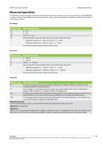
NORIS Automation GmbH Measured quantities The following measured quantities with the specified signal measurement ranges can be connected directly to type NORIMETER 3 indicators without using additional measuring transducers. Other measured quantities are available on request with additional measuring transducers. DC voltage Indicator type Measurement range Special calibration: freely selectable within the specified range limits below. • Minimum range limit: 0…100 mV or -50 mV…0…+50 mV • Maximum range limit: 0…300 V or -150 V …0… +150 V For further information please read the technical data....
Open the catalog to page 7All NORIS Group GmbH catalogs and brochures
 Unique Yacht Automation
16 Pages
 Energy storage solutions
2 Pages
 Datasheet TAV131
3 Pages
 Datenblatt VFS5
2 Pages
 Datasheet PAx9
6 Pages
 Datasheet RG5
2 Pages
 Datasheet VFW5
2 Pages
 Datasheet RP5, RPT5
2 Pages
 Datasheet NIR3 NIQ3
20 Pages
 Datasheet VD61
6 Pages
 Datasheet FA13
14 Pages
 Energy Storage System
2 Pages
 NORIS Marine Overview
13 Pages
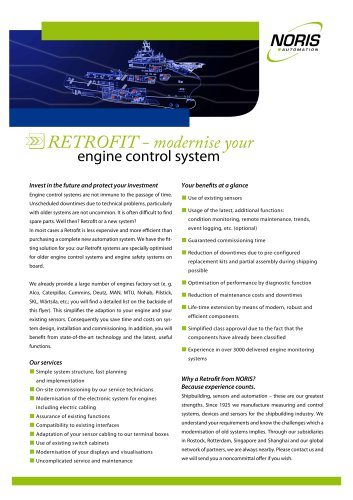 RETROFIT - modernise your
2 Pages
 Datasheet NORISYS 4 LA4
4 Pages
 Datasheet NORISYS 4 LS4
4 Pages
 Datasheet NORISYS 4 LT4
4 Pages
 Datasheet FA54
11 Pages
 NORIS Brochure
15 Pages
 Datasheet TP31 TH31
5 Pages
 Datasheet EOT
6 Pages
 Datasheet NORISPEED FMN6
2 Pages
 Datasheet DWA
4 Pages
 Datasheet TP23
4 Pages
 Datasheet VF5
2 Pages
 Flyer NORISYS 4 CPU
2 Pages
 Datasheet RFW5
2 Pages
 NORISYS 4 - PLC Deep Sea
2 Pages
 Datasheet RTK5
2 Pages
 Datasheet RFJ5
2 Pages
 Datasheet VTK5
2 Pages
 Datasheet RF5
2 Pages
 Datasheet RI5
2 Pages
 Datasheet RFG5
2 Pages
 Datasheet VPT5
2 Pages
 Datasheet RH5
2 Pages
 Datasheet VFS5
2 Pages
 Datasheet RH41M
2 Pages
 Datasheet RW5
2 Pages
 Datasheet VMP70
3 Pages
 Datasheet VP5
2 Pages
 Datasheet NADS3
2 Pages
 Datasheet NAD2
2 Pages
 Datasheet NAD1
2 Pages
 Flyer NORISYS 4
2 Pages


Archived catalogs
 Datasheet GE14
2 Pages
 Datasheet GE12
2 Pages
- Boat sensor
- Boat indicator
- Analog indicator
- Temperature sensor
- Boat battery
- Control lever
- Boat monitoring and control panel
- Engine control lever
- Ship sensor
- Boat control lever
- Lithium battery
- Digital control lever
- Boat display
- Ship software
- Multi-lever control lever
- Single-lever control lever
- Ship control panel
- Multi-function display
- Yacht monitoring panel