 Website:
NORIS Group GmbH
Group: Noris Group
Catalog excerpts

Speed pickup with two square wave outputs and rotational direction relay NADS3... • Speed pickup with square wave output signal and rotational direction relay Speed Pickup • Can be mounted in place of a tachogenerator • Robust design • Maintenance-free • Integrated signal amplifier • Powerful, interference-immune output signal • 60 pulses per revolution • Push-pull output stage as output • Can be loaded with 50 mA SINK and 20 mA LOAD • High EMC protection for harsh electrical environments • Large operating temperature range -25 °C ... +85 °C • Complies with • Matching evaluators can be supplied Speed pickup type series NADS3... Functional principle of the speed pickup Speed and frequency characteristics Speed pickups are maintenance-free devices for converting rotary The drive shaft powers a pulse disc with 60 segments. Magnetic motion into square wave signals. The drive shaft of the speed pickup is sensing of the segments produces a square wave signal, whereby the connected directly to the speed source (e.g. motor, generator) by means frequency is proportional to the speed of the drive shaft. At 1,000 rpm, the 60 segments generate a frequency of 1,000 Hz. The speed is converted into a square wave signal using a signal amplifier. Two square wave signals with a phase offset of 90° are available. These enable the direction of rotation to be detected. The square wave signal can be evaluated or converted by several devices. Connection to PLC digital counter assemblies is also possible. An integrated rotational direction relay outputs the direction of rotation directly as a binary value. Design and mounting The speed pickups feature a particularly robust design. They have an enclosed metal housing and an impact-resistant plastic terminal box with a screwed cable gland. The degree of protection is IP66. The electrical connections are made via screw terminals in the plastic terminal box, also with IP66 degree of protection. The device is connected to the drive shaft via a coupling (not included in the scope of delivery). Flexible couplings are recommended to compensate for shaft misalignment. The pickup is mounted using a bracket or installation flange for standard spigots with Ø 40 mm. The NADS3... speed pickup can be used instead of tachogenerators if a speed-proportional square wave signal is required. Speed pickup output The output signal is a noise-immune square wave signal, whereby the frequency is proportional to the speed. The voltage range is between the supply voltage and is load-dependent. The pulse duty factor is approx. 50%. The output circuit is a push-pull output stage. Short-circuit protection is provided by a 130 PTC resistor. Spurious pulses are intercepted by an internal varistor operating relative to the negative pole. The push-pull output stage can be used as an NPN output (SINK) and as a PNP output (LOAD). The output voltage is galvanically connected to the supply voltage. The rotational direction relay contact is a flo
Open the catalog to page 1
Dimensions, Connection, Diagrams Type series NADS3... Direction of rotation detection Relay contact closed open clockwise anti-clockwise Type code / standard versions Device series NA 3 Spigot 0 40 mm, housing 0 80 and length 76 mm NADS 3 -13-K (NADS3-13-K) (Only standard versions, other customised versions on request) NORIS Automation GmbH Muggenhofer StraRe 95 90429 Nuremberg GERMANY info@noris-group.com www.noris-group.com V01.02 - 05/2016 Errors and omissions expected.
Open the catalog to page 2All NORIS Group GmbH catalogs and brochures
-
Unique Yacht Automation
16 Pages
-
Energy storage solutions
2 Pages
-
Datasheet TAV131
3 Pages
-
Datenblatt VFS5
2 Pages
-
Datasheet PAx9
6 Pages
-
Datasheet RG5
2 Pages
-
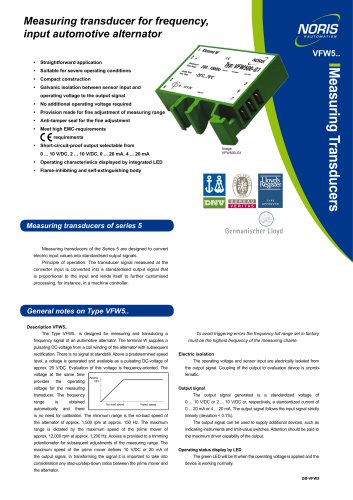
Datasheet VFW5
2 Pages
-
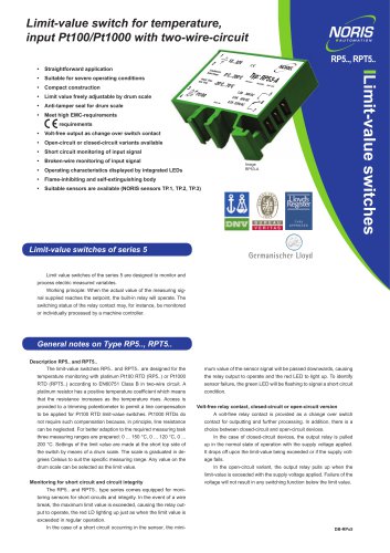
Datasheet RP5, RPT5
2 Pages
-
Datasheet NIR3 NIQ3
20 Pages
-
Datasheet VD61
6 Pages
-
Datasheet FA13
14 Pages
-
Datasheet NIQ31
16 Pages
-
Energy Storage System
2 Pages
-
NORIS Marine Overview
13 Pages
-
Datasheet NORISYS 4 LA4
4 Pages
-
Datasheet NORISYS 4 LS4
4 Pages
-
Datasheet NORISYS 4 LT4
4 Pages
-
Datasheet FA54
11 Pages
-
RETROFIT - modernise your
2 Pages
-
NORIS Brochure
15 Pages
-
Datasheet TP31 TH31
5 Pages
-
Datasheet EOT
6 Pages
-
Datasheet NORISPEED FMN6
2 Pages
-
Datasheet DWA
4 Pages
-
Datasheet TP23
4 Pages
-
Datasheet VF5
2 Pages
-
Flyer NORISYS 4 CPU
2 Pages
-
Datasheet RFW5
2 Pages
-
NORISYS 4 - PLC Deep Sea
2 Pages
-
Datasheet RTK5
2 Pages
-
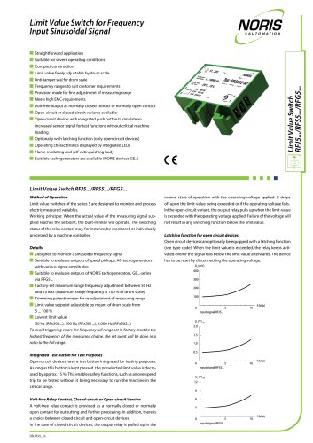
Datasheet RFJ5
2 Pages
-
Datasheet VTK5
2 Pages
-
Datasheet RF5
2 Pages
-
Datasheet RI5
2 Pages
-
Datasheet RFG5
2 Pages
-
Datasheet VPT5
2 Pages
-
Datasheet RH5
2 Pages
-
Datasheet VFS5
2 Pages
-
Datasheet RH41M
2 Pages
-
Datasheet RW5
2 Pages
-
Datasheet VMP70
3 Pages
-
Datasheet VP5
2 Pages
-
Datasheet NAD2
2 Pages
-
Datasheet NAD1
2 Pages
-
Flyer NORISYS 4
2 Pages
Archived catalogs
-
Datasheet GE12
2 Pages
-
Datasheet GE14
2 Pages


