
- Catalogs
- NORIS Group GmbH
- Datasheet NAD2

- Company
- Products
- Catalogs
- News & Trends
- Exhibitions
Datasheet NAD2
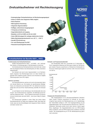
Datasheet NAD2
The document describes the NORIS Drehzahlaufnehmer (speed sensor) models NAD1 and NAD2, which are maintenance-free devices designed to convert rotational movements into square wave signals. Key specifications include a cost-effective design, small form factor, integrated signal amplifier, and robust output signal. The sensors are capable of operating in harsh environments up to IP67 and have a wide operating temperature range from -25°C to +100°C. They provide 15 pulses per revolution and are equipped with a push-pull output stage, capable of handling 50 mA SINK and 20 mA LOAD.
Functionality:
The speed sensors work by connecting the drive shaft directly or indirectly to the speed source (e.g., motor, generator) via a flexible shaft. The rotational speed is converted into a square wave signal by a signal amplifier, which can be evaluated or transformed by various devices, including digital counter modules of a PLC.
Design and Installation:
The sensors feature a compact and robust design with a closed metal housing, meeting IP67 protection standards. Electrical connections are made via a Euro M12x1 plug connection. Depending on the model, the connection to the drive shaft is made via a tongue or slot connection. The NAD1 model is mounted by screwing and securing with a locknut, while the NAD2 model uses a holder for a Ø 30 mm pin.
Speed and Frequency Characteristics:
The drive shaft rotates a perforated disc with 15 holes, generating a square wave signal through magnetic scanning. The frequency of this signal is proportional to the rotational speed, with 1,000 rpm corresponding to a frequency of 250 Hz.
Output:
The output signal is a robust square wave signal with a frequency proportional to the rotational speed. The output stage is a push-pull configuration, with short-circuit protection provided by a 130 PTC resistor. The output can be configured as either NPN or PNP, and the output voltage is galvanically connected to the operating voltage.
Technical Data:
The sensors operate with a supply voltage of 10 to 32 V/DC, with a nominal voltage of 24 V/DC ±5%. They have integrated polarity and overvoltage protection. The input speed range is 0 to 6,000 rpm, corresponding to 0 to 1,500 Hz. The output signal is a NORIS standard square wave, with high and low output levels specified at various load currents.
Environmental Influences:
The sensors are designed to withstand a wide range of environmental conditions, including operating temperatures from -25°C to +100°C, vibration resistance according to DIN IEC60068-T2-6, and shock resistance according to DIN IEC60068-T2-27. They meet various EMC standards, including ESD, RF immunity, burst, surge, and conducted disturbances.
Additional Information:
The sensors are compliant with CE requirements and have a recommended storage temperature range of -25°C to +70°C. They can be mounted in any position and have a weight of approximately 80 g. The document also includes detailed mechanical and electrical connection diagrams.
Catalog excerpts

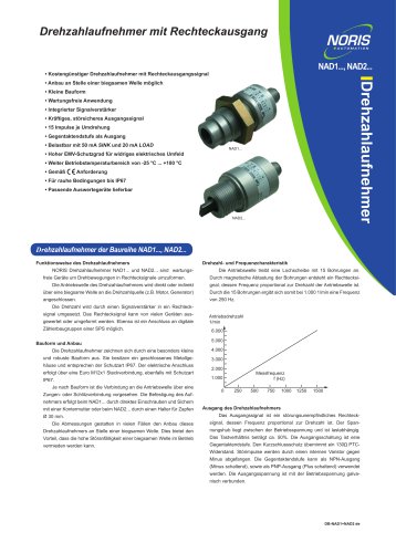
• Kostengünstiger Drehzahlaufnehmer mit Rechteckausgangssignal • Anbau an Stelle einer biegsamen Welle möglich • Kleine Bauform • Wartungsfreie Anwendung • Integrierter Signalverstärker • Kräftiges, störsicheres Ausgangssignal • 15 Impulse je Umdrehung • Gegentaktendstufe als Ausgang • Belastbar mit 50 mA SINK und 20 mA LOAD • Hoher EMV-Schutzgrad für widriges elektrisches Umfeld • Weiter Betriebstemperaturbereich von -25 °C ... +100 °C • Gemäß • Für rauhe Bedingungen bis IP67 • Passende Auswertegeräte lieferbar Drehzahlaufnehmer der Baureihe NAD1..., NAD2... Funktionsweise des Drehzahlaufnehmers NORIS Drehzahlaufnehmer NAD1... und NAD2... sind wartungsfreie Geräte um Drehbewegungen in Rechtecksignale umzuformen. Drehzahl- und Frequenzcharakteristik Die Antriebswelle treibt eine Lochscheibe mit 15 Bohrungen an. Durch magnetische Abtastung der Bohrungen entsteht ein Rechtecksi- Die Antriebswelle des Drehzahlaufnehmers wird direkt oder indirekt gnal, dessen Frequenz proportional zur Drehzahl der Antriebswelle ist. über eine biegsame Welle an die Drehzahlquelle (z.B. Motor, Generator) Durch die 15 Bohrungen ergibt sich somit bei 1.000 1/min eine Frequenz Die Drehzahl wird durch einen Signalverstärker in ein Rechtecksignal umgesetzt. Das Rechtecksignal kann von vielen Geräten ausgewertet oder umgeformt werden. Ebenso ist ein Anschluss an digitale Zählerbaugruppen einer SPS möglich. Bauform und Anbau Die Drehzahlaufnehmer zeichnen sich durch eine besonders kleine und robuste Bauform aus. Sie besitzen ein geschlossenes Metallge- häuse und entsprechen der Schutzart IP67. Der elektrische Anschluss erfolgt über eine Euro M12x1 Steckverbindung, ebenfalls mit Schutzart IP67. Je nach Bauform ist die Verbindung an die Antriebswelle über eine Zungen- oder Schlitzverbindung vorgesehen. Die Befestigung des Aufnehmers erfolgt beim NAD1... durch direktes Einschrauben und Sichern mit einer Kontermutter oder beim NAD2... durch einen Halter für Zapfen Ø 30 mm. Die Abmessungen gestatten in vielen Fällen den Anbau dieses Drehzahlaufnehmers an Stelle einer biegsamen Welle. Dies bietet den Vorteil, dass die hohe Störanfälligkeit einer biegsamen Welle im Betrieb vermieden werden kann. Ausgang des Drehzahlaufnehmers Das Ausgangssignal ist ein störungsunempfindliches Rechtecksignal, dessen Frequenz proportional zur Drehzahl ist. Der Spannungshub liegt zwischen der Betriebsspannung und ist lastabhängig. Das Tastverhältnis beträgt ca. 50%. Die Ausgangsschaltung ist eine Gegentaktendstufe. Den Kurzschlussschutz übernimmt ein 130 PTCWiderstand. Störimpulse werden durch einen internen Varistor gegen Minus abgefangen. Die Gegentaktendstufe kann als NPN-Ausgang (Minus schaltend), sowie als PNP-Ausgang (Plus schaltend) verwendet werden. Die Ausgangsspannung ist mit de
Open the catalog to page 1
Technische Daten MaRe, Anschluss, Schaltbild Baureihe NAD1... und NAD2... NAD1-1125-E NAD2-1225-E Anschlusskabel (nicht im Lieferumfang enthalten) Typenschlussel / Standardvarianten Geratereihe Drehzahlaufnehmer in mechanischer Bauform Digital Hall Prinzip Elektrischer Anschluss - E EURO M12 x 1, Stiftstecker 5-pol., Kontakte vergoldet NAD 1 -1125 -E (NAD1-1125-E) (nur Standardausfuhrungen, weitere nach Kundenwusch lieferbar) NORIS Automation GmbH Muggenhofer Strasse 95 90429 Nurnberg GERMANY
Open the catalog to page 2All NORIS Group GmbH catalogs and brochures
 Unique Yacht Automation
16 Pages
 Energy storage solutions
2 Pages
 Datasheet TAV131
3 Pages
 Datenblatt VFS5
2 Pages
 Datasheet PAx9
6 Pages
 Datasheet RG5
2 Pages
 Datasheet VFW5
2 Pages
 Datasheet RP5, RPT5
2 Pages
 Datasheet NIR3 NIQ3
20 Pages
 Datasheet VD61
6 Pages
 Datasheet FA13
14 Pages
 Datasheet NIQ31
16 Pages
 Energy Storage System
2 Pages
 NORIS Marine Overview
13 Pages
 RETROFIT - modernise your
2 Pages
 Datasheet NORISYS 4 LA4
4 Pages
 Datasheet NORISYS 4 LS4
4 Pages
 Datasheet NORISYS 4 LT4
4 Pages
 Datasheet FA54
11 Pages
 NORIS Brochure
15 Pages
 Datasheet TP31 TH31
5 Pages
 Datasheet EOT
6 Pages
 Datasheet NORISPEED FMN6
2 Pages
 Datasheet DWA
4 Pages
 Datasheet TP23
4 Pages
 Datasheet VF5
2 Pages
 Flyer NORISYS 4 CPU
2 Pages
 Datasheet RFW5
2 Pages
 NORISYS 4 - PLC Deep Sea
2 Pages
 Datasheet RTK5
2 Pages
 Datasheet RFJ5
2 Pages
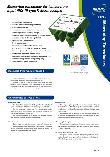 Datasheet VTK5
2 Pages
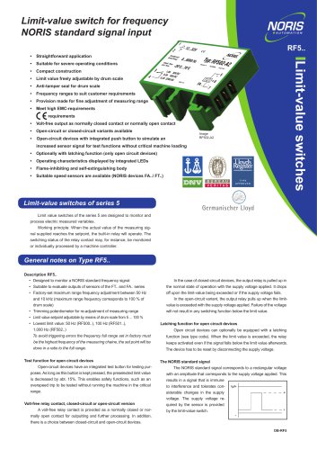 Datasheet RF5
2 Pages
 Datasheet RI5
2 Pages
 Datasheet RFG5
2 Pages
 Datasheet VPT5
2 Pages
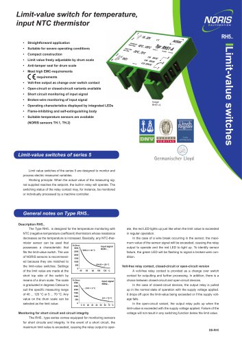 Datasheet RH5
2 Pages
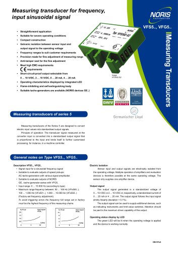 Datasheet VFS5
2 Pages
 Datasheet RH41M
2 Pages
 Datasheet RW5
2 Pages
 Datasheet VMP70
3 Pages
 Datasheet VP5
2 Pages
 Datasheet NADS3
2 Pages
 Datasheet NAD1
2 Pages
 Flyer NORISYS 4
2 Pages













Archived catalogs
 Datasheet GE14
2 Pages
 Datasheet GE12
2 Pages
- Boat sensor
- Boat indicator
- Analog indicator
- Temperature sensor
- Boat battery
- Control lever
- Boat monitoring and control panel
- Engine control lever
- Ship sensor
- Lithium battery
- Boat control lever
- Nautical display
- Digital control lever
- Boat display
- Ship software
- Single-lever control lever
- Multi-lever control lever
- Ship control panel
- Yacht monitoring panel
- Multi-function display