- Catalogs
- NORIS Group GmbH
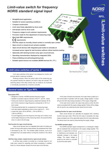
- Datasheet DWA-Q Rotary position sensor with ohmic signal output or voltage output
Datasheet DWA-Q Rotary position sensor with ohmic signal output or voltage output

Datasheet DWA-Q Rotary position sensor with ohmic signal output or voltage output
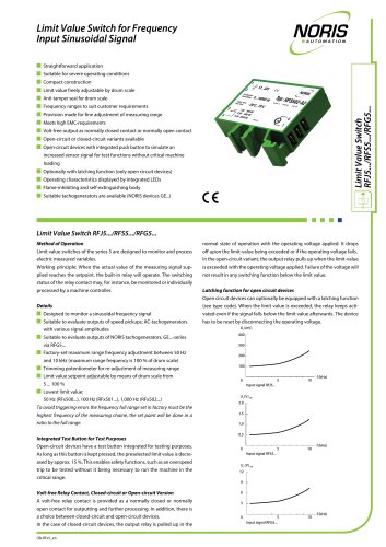
- Type R1: Provides 0 to 2 kΩ signal outputs with a linear acquisition angle.
- Type U2: Provides 2 to 10 VDC signal outputs with crossed characteristic curves, requiring an external power supply.
Catalog excerpts

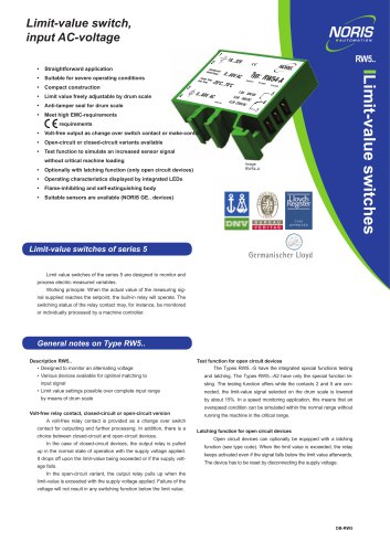
Rotary position sensor with ohmic signal output or voltage output Change in resistance on the voltage divider, hall-effect Measuring range Type R1: 50° ... 360° in 10° steps (linear acquisition angle) Type U2: 50° ... 360° in 10° steps (linear acquisition angle) Rotation angle 360° without mechanical limitation Output signal Type R1: 2 signal outputs: 0 ... 2 kΩ Type U2: 2 signal outputs: 2 ... 10 VDC, crossed characteristic curves Operating temperature Protection class Electrical connection Design Q1: Push-in terminals for max. 2.5 mm², with M20 screw connection as per DIN EN 50262 for cable diameter 9 to 13 mm Design Q2: 4x 2x 0.5 mm² fixed connection cables, 3 m in length, with M16 screw connection as per DIN EN 50262 Rotary position sensor DWA-Q Measuring principle Special features Scope of application The type DWA-Q rotary position sensors are robust, maintenance-free sensors that are particularly used in the Shipbuilding industry and machinery and plant engineering industry to convert the mechanical rotation angle of a shaft into an electrical signal (e.g. for measuring the rudder angle or adjusting the pitch). • Reference position mark • Maintenance-free operation • No reference run necessary • Potential-separated channels Measuring principle The instrument shaft is connected to a double sensor. Depending on requirements, the angle position that can be acquired electronically (50° ... 360° in 10° steps (linear acquisition angle)) must be selected and adjusted within a mechanical revolution. The version with ohmic resistor connection provides a passive electrical signal; the version with analogue current output provides an active electrical signal. Datasheet DB-DWA-Q-EN | V01.01 | 15/12/2017 | Valid from product revision B | www.noris-group.com | sales@
Open the catalog to page 1
| Dimensioned drawing, connection and wiring diagrams NORIS Automation GmbH Dimensioned drawing, connection and wiring diagrams DWA-Q1 (design Q1) dimensions and wiring diagram for push-in terminals up to max. 2.5 mm2 C A: Length 115 mm B: Length 40 mm C: Length 25 mm D: Ø 40h7 mm E: Ø 12h7 mm F: 62x62 mm G: Length 30 mm Wiring diagram for ohmic resistor connection Wiring diagram for analogue voltage output A: Length 62 mm B: Length 92 mm C: Length 62 mm D: Ø 70 mm E: 4 x M6x7 mm F: 90° Information on the connection diagram: Tap-off point on the voltage divider in arrow direction when the drive...
Open the catalog to page 2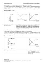
NORIS Automation GmbH Dimensioned drawing, connection and wiring diagrams | Type DWA-Q...-R1 in version with ohmic signal output, passive electrical signal A centre-tapped potentiometer serves as the measuring element. The change in resistance corresponds linearly to the angle position within the electrical acquisition range. A power supply is not necessary for this. The ohmic signal for the respective acquisition range of the DWA can be converted into a standard 2–10 V DC signal by means of a signal amplifier (e.g. NORIS SA502-3G) (see following figures). Diagram of the DWA-Q…-R1 range R [Ω]...
Open the catalog to page 3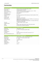
NORIS Automation GmbH Technical data Common technical data Measuring principle Change in resistance on the voltage divider, hall-effect Rotation angle 360° without mechanical limitation Vibration resistance 4 g DIN IEC 60068-6 increased stress, characteristic curve 2 (2 ... 100 Hz) Shock resistance (impact) Climatic test Operating temperature Storage temperature -40 ... 70°C (max. peak values within 30 days/year at relative humidity of 5–95%) Insulation voltage Protection class Electrical connection Design Q1: Push-in terminals for max. 2.5 mm², with M20 screw connection as per DIN EN 50262 for...
Open the catalog to page 4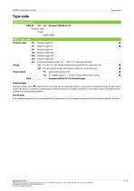
NORIS Automation GmbH Type code Type code structure DWA 90 Rotation angle Design Signal output DWA... type code Rotation angle Customised rotation angle: 10° … 360° in 10° steps (special type) Output signal 62 x 62 x 115 mm design with terminals and Ø 40 mm connection pin 62 x 62 x 66 mm design with cable and Ø 30 mm connection pin -R1 -U2 Dual potentiometer 2 kΩ 2 x voltage output 2 … 10 VDC, crossed characteristic curves Example: DWA70-Q1-U2 (Preferred type) Preferred types Features marked with a symbol at the end of the line are preferred features. If you select a preferred feature for each...
Open the catalog to page 5All NORIS Group GmbH catalogs and brochures
 Unique Yacht Automation
16 Pages
 Energy storage solutions
2 Pages
 Datasheet TAV131
3 Pages
 Datenblatt VFS5
2 Pages
 Datasheet PAx9
6 Pages
 Datasheet RG5
2 Pages
 Datasheet VFW5
2 Pages
 Datasheet RP5, RPT5
2 Pages
 Datasheet NIR3 NIQ3
20 Pages
 Datasheet VD61
6 Pages
 Datasheet FA13
14 Pages
 Datasheet NIQ31
16 Pages
 Energy Storage System
2 Pages
 NORIS Marine Overview
13 Pages
 RETROFIT - modernise your
2 Pages
 Datasheet NORISYS 4 LA4
4 Pages
 Datasheet NORISYS 4 LS4
4 Pages
 Datasheet NORISYS 4 LT4
4 Pages
 Datasheet FA54
11 Pages
 NORIS Brochure
15 Pages
 Datasheet TP31 TH31
5 Pages
 Datasheet EOT
6 Pages
 Datasheet NORISPEED FMN6
2 Pages
 Datasheet DWA
4 Pages
 Datasheet TP23
4 Pages
 Datasheet VF5
2 Pages
 Flyer NORISYS 4 CPU
2 Pages
 Datasheet RFW5
2 Pages
 NORISYS 4 - PLC Deep Sea
2 Pages
 Datasheet RTK5
2 Pages
 Datasheet RFJ5
2 Pages
 Datasheet VTK5
2 Pages
 Datasheet RF5
2 Pages
 Datasheet RI5
2 Pages
 Datasheet RFG5
2 Pages
 Datasheet VPT5
2 Pages
 Datasheet RH5
2 Pages
 Datasheet VFS5
2 Pages
 Datasheet RH41M
2 Pages
 Datasheet RW5
2 Pages
 Datasheet VMP70
3 Pages
 Datasheet VP5
2 Pages
 Datasheet NADS3
2 Pages
 Datasheet NAD2
2 Pages
 Datasheet NAD1
2 Pages
 Flyer NORISYS 4
2 Pages


Archived catalogs
 Datasheet GE14
2 Pages
 Datasheet GE12
2 Pages
- Boat sensor
- Boat indicator
- Analog indicator
- Temperature sensor
- Boat battery
- Control lever
- Boat monitoring and control panel
- Engine control lever
- Ship sensor
- Boat control lever
- Lithium battery
- Nautical display
- Digital control lever
- Boat display
- Ship software
- Multi-lever control lever
- Single-lever control lever
- Ship control panel
- Multi-function display
- Yacht monitoring panel