
- Catalogs
- Ningbo Shanbei Technology Co.,Ltd
- WSS-R68_Non-contact rudder angle feedback_User Manual_EN_V1.0

WSS-R68_Non-contact rudder angle feedback_User Manual_EN_V1.0
1 /16Pages
WSS-R68_Non-contact rudder angle feedback_User Manual_EN_V1.0
1 /16Pages
Catalog excerpts

User manual Ningbo SHANBEI Technology Co.,Ltd
Open the catalog to page 1
Warning: Before using this product, please refer to the important safety information in the user manual and review all warnings, limitations and disclaimers. This product is no substitute for proper training and careful seamanship. Proper installation and proper use of the equipment is the responsibility of the owner to avoid accidents, personal injury or property damage. The user of this product is solely responsible for compliance with maritime safety practices. The owner is solely responsible for installing and using the equipment in a manner that will not cause accidents, personal injury...
Open the catalog to page 2
Product appearance • • Product composition • Product size drawing * Product wiring diagram
Open the catalog to page 3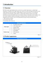
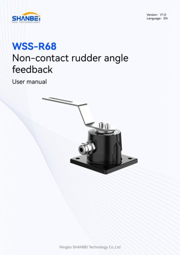
WSS-R68 rudder Angle feedback device, also known as rudder Angle sensor or rudder Angle transmitter, is installed in the rudder engine room, which can convert the Angle and direction of the rudder blade into electrical signals or digital signals to send to the receiver. It is an important component of the automatic rudder system or rudder Angle indication system, and its Angle acquisition accuracy and stability have a very important impact on the ship's control. Products using non-contact magnetic induction technology, no mechanical wear, extend the service life. The sampling accuracy reaches...
Open the catalog to page 4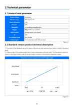
1. The shell of the feedback device is made of aluminum alloy, and the main shaft is made of stainless steel; 2. Output mode: The analog output has a linear relationship with the scale. The theoretical output is shown in the figure below, and the actual output is shown in the factory inspection report. Theoretical current output curve of ±45° rudder Angle
Open the catalog to page 7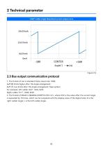
±360° rudder Angle theoretical current output curve buff [0] 8 bits higher after lOx Angle enlargement; buff [1] Low 8 bits after lOx Angle enlargement; Tape symbol For example: left rudder 36.3° : Oxfe; 0x95 Right rudder 15.7° : 0x00; 0x9d 2. The format of RS422 is $AGRSA,XXXR*hh<CR><LF>, where XXX is the value after the current Angle is expanded by 10 times, which can be compared with the display value of the digital tube; R is the right rudder Angle, L is the left rudder Angle.
Open the catalog to page 8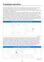
The rudder Angle feedback should be flexibly installed according to the type of steering gear, fixed with M8 triple combination screws and nuts, and connected with a threaded rod to form a parallelogram connecting rod structure to ensure that the rotation Angle of the rudder is equal to the rotation Angle of the feedback rod. 1. Installation of tilting cylinder steering gear rudder Angle feedback device: tilting cylinder steering gear rudder Angle feedback device is suitable for installation on the front and rear side of the rudder rod, please adjust according to the specific layout and position...
Open the catalog to page 9
1. After the installation is complete, check whether the connections are reliable. 2. Switch on the power supply, manually hit the rudder, compare the rudder Angle feedback value and the scale value of the hydraulic steering machine, and constantly adjust the extension length of the dial rod and the length of the connecting rod to ensure 1 to 1 transmission.
Open the catalog to page 10
This product has been put into operation since the use, basically no fault, with our statistics, the after-sales problem is basically due to wiring errors, resulting in normal use, in addition, there is no technical fault. Customers in the use of the process, if you find technical problems, please promptly communicate with our technical personnel.
Open the catalog to page 11
6.1 Safety protection devices and precautions 1. The important position of this product has been tightened seal processing at the factory, shall not be disassembled without permission, if the seal is damaged, any product quality problems are borne by the buyer. 2. Once the product fails to operate normally, please stop using and disconnect the power supply immediately, and contact our after-sales service engineer for a solution. 6.2 Troubleshooting procedures and methods 1. In the process of use, there is an unsolvable fault problem, contact our after-sales service engineer. 2. During the warranty...
Open the catalog to page 12
7.1 Daily maintenance and maintenance In the daily non-use state, attention should be paid to the maintenance of this product. Through maintenance, maintenance can improve the service fife of the product, the specific maintenance and maintenance methods are as follows: 1. Wipe the surface of the product regularly with a dry rag to ensure that the outside of the product is clean and tidy. 2. Regularly check the lubrication of fisheye bearings and other parts, and apply appropriate grease. 1. Stop using the device when there is a problem. Contact our after-sales engineer. 2. The input voltage shall...
Open the catalog to page 13
Physical damage to the product caused by violent shaking and collision should be avoided during transportation. Room temperature, dry, cool environment. The warranty period of this product is 12 months from the date of receipt of the goods by the buyer. Based on the date of receipt of documents for express delivery or the date of receipt of invoice.
Open the catalog to page 14
9.1 Phone number of the after-sales engineer Manufacturer: Ningbo SHANBEI Technology Co., LTD Address: A2-902, R&D Park, High-tech Zone, Ningbo Postal Code: 310001 Tel: (0574) 87182781 Fax: (0574) 87182781
Open the catalog to page 15
For more information, please visit: www.shanbei-tech.com Ningbo SHANBEI Technology Co.,Ltd Add: 902 Area A, R&D Park, High-tech Zone, Ningbo, Zhejiang, China Tel: 0574-87186781 /18067343163
Open the catalog to page 16All Ningbo Shanbei Technology Co.,Ltd catalogs and brochures
- Analog indicator
- Shanbei Technology control lever
- Steering compass
- Shanbei Technology engine control lever
- Boat steering compass
- Ship sensor
- Boat control lever
- Shanbei Technology digital control lever
- Built-in steering compass
- Mechanical control lever
- Shanbei Technology single-lever control lever
- Multi-lever control lever
- Digital indicator
- Shanbei Technology surface-mount control lever
- Shanbei Technology ship control lever
- Ship indicator
- Motor indicator
- Ship joystick
- Rudder angle indicator
- Multi-function joystick