
- Catalogs
- Ningbo Shanbei Technology Co.,Ltd
- WPM-P_Shaft power meter_User manual_EN_V2.0

WPM-P_Shaft power meter_User manual_EN_V2.0
1 /52Pages

WPM-P_Shaft power meter_User manual_EN_V2.0
1 /52Pages
Catalog excerpts

User manual Ningbo SHANBEI Technology Co.,Ltd
Open the catalog to page 1
Warning: Before using this product, please refer to the important safety information in the user manual and review all warnings, limitations and disclaimers. This product is no substitute for proper training and careful seamanship. Proper installation and proper use of the equipment is the responsibility of the owner to avoid accidents, personal injury or property damage. The user of this product is solely responsible for compliance with maritime safety practices. The owner is solely responsible for installing and using the equipment in a manner that will not cause accidents, personal injury...
Open the catalog to page 2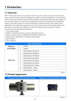
WPM-P shaft power meter is an instrument used for long-term continuous measurement of speed, torque, power and thrust (optional). Designed according to maritime specifications, it can be used for power monitoring of ship main engine shafting, propeller and generator shaft, providing reliable and real-time data support for various power management systems and energy efficiency management systems. The product adopts non-contact measurement, wireless induction power supply, strong adaptability, the longest data storage time can be up to 5 years, used in Marine diesel engines and gear boxes, mining...
Open the catalog to page 5
Make sure that the power supply is disconnected before wiring! 1. Prepare crimping terminals and cables. 2. Type D grounding is used. 3. Connect the power terminal. Connect the + and - of the DC power supply to the V+ and V-terminals of the product, and the PE of the power supply to the common end of the device ground.
Open the catalog to page 7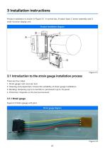
Product installation is shown in Figure 3.1: A control box, B stator base, C stator assembly and D multi-function display unit. 3.1 Introduction to the strain gauge installation process There are four steps: 1. Strain gauge: test once per axis 2. Cleaning and preparation: Ensure the suitability of strain gauge installation 3. Bonding: temporary (up to 6 months) or permanent (up to 10 years) 4. Protection: Depends on the test environment Figure 3.2 Strain gauge with joint.
Open the catalog to page 11
The strain gauge with joint is shown in Table 3.1.
Open the catalog to page 12
Strain gauges with joints are shown in Table 3.4.
Open the catalog to page 13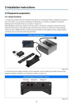
1. Familiarize yourself with and understand the system on the desktop before installing the system on site in the cabin. Lay out all the components of the system on a table or workbench so that the bending side of the stator faces up, as shown in Figure 3.3. Warning! Before continuing, make sure the main power connection is isolated. Connect the power cable from the stator to the machine side control box and connect it to the multi-function display using the CAN or RS485 interface, directly through the APP on the interface. (Or PC, laptop directly use the browser to open the monitoring interface)...
Open the catalog to page 14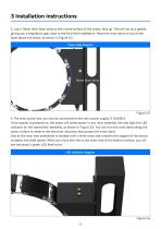
4. The side control box can now be connected to the main power supply (110/230V). If the system is powered on, the stator will sense power in any rotor assembly link and light the LED indicator on the transmitter assembly, as shown in Figure 3.6. You can turn the rotor band along the stator surface to observe the electrical induction that powers the rotor band. One of the rotor belt assemblies is marked with a white cross and contains the magnet of the sensor to detect the shaft speed. When you move this link to the lower end of the stator's surface, you will see the stator's green LED flash...
Open the catalog to page 15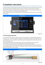
After completing this test, you have tested the transmitter and test receiver and have some familiarity with the suite. Display diagram @iorqu? mrysi ■ Kar^mi System calculator calculator calculator setting Spindle i nner diameter Not avertable Maximum torque: Not available spindle material: OOOOOOOOOOO Young's modulus: OOOOOOOOOOO Strain coefficient: OOOOOOOOOOO Calibration valuer OOOOOOOOOOO 1. To install the strain gauge, you need to prepare the strain gauge on a small tempered glass plate with mylar tape. It is best to complete this stage in a well-lit clean room before entering the site....
Open the catalog to page 16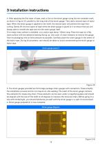
4. After applying the first layer of tape, mark a line on the strain gauge using the non-erasable mark, as shown in Figure 3.9, parallel to the long side of the strain gauge. Then add a second layer of mylar tape. When the strain gauge is applied to the shaft, the second layer will prevent the tape from curling. Gently lift the two layers of tape while the strain gauge is glued to it to ensure that you are always able to handle the tape and not the strain gauge itself. If no ready clean surface is available: cut a mylar tape about 1 50mm long. Place the tape on a flat, clean surface with the...
Open the catalog to page 17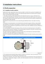
Selecting the right measurement area on the drive shaft is critical to the success of installation and data recovery. Where feasible, the area to be measured shall transmit the maximum level of torque/ strain to be measured through the shaft. 1. The stator mounting column shall be fixed to the ship floor structure using 2 x M16 bolts. The position relationship between the stator mounting column and the drive shaft needs to be within the size range provided by the benchmark electronics to ensure that the final full system components are properly aligned after assembly. Adjustments in these dimensions...
Open the catalog to page 18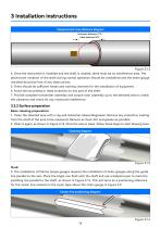
Basic cleaning preparation: 1. Clean the selected area with a rag and industrial cleaner/degreaser. Remove any protective coating from the shaft of the area to be measured. Remove as much dirt and grease as possible. 2. Clean it again, as shown in Figure 3.13. Once the area is clean, follow these steps to start drawing lines.
Open the catalog to page 19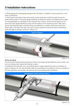
4. When aligning the torque gauge assembly with the shaft, it is helpful to mark a guide line on the shaft circumference. 5. Plastic tape is provided to help mark precise circular guide lines. Unfold the shaft around the plastic belt provided. If the torque gauge assembly, the guide line needs to be aligned with an edge. If a mounting platform is prepared on the container floor, check to ensure that the guide line will allow the torsion gauge assembly to align with the position of the mounting column. Take care to ensure that the plastic tape is laid flat without any distortion or collision....
Open the catalog to page 20All Ningbo Shanbei Technology Co.,Ltd catalogs and brochures























- Analog indicator
- Shanbei Technology control lever
- Steering compass
- Shanbei Technology engine control lever
- Boat steering compass
- Ship sensor
- Boat control lever
- Shanbei Technology digital control lever
- Built-in steering compass
- Mechanical control lever
- Shanbei Technology single-lever control lever
- Multi-lever control lever
- Digital indicator
- Shanbei Technology surface-mount control lever
- Shanbei Technology ship control lever
- Ship indicator
- Motor indicator
- Ship joystick
- Rudder angle indicator
- Multi-function joystick