
- Catalogs
- Ningbo Shanbei Technology Co.,Ltd
- WLF-90_Propulsion control lever_User manual_EN_V1.5

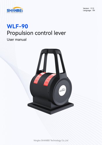
WLF-90_Propulsion control lever_User manual_EN_V1.5
1 /21Pages
WLF-90_Propulsion control lever_User manual_EN_V1.5
1 /21Pages
Catalog excerpts

User manual Ningbo SHANBEI Technology Co.,Ltd
Open the catalog to page 1
Warning: Before using this product, please refer to the important safety information in the user manual and review all warnings, limitations and disclaimers. This product is no substitute for proper training and careful seamanship. Proper installation and proper use of the equipment is the responsibility of the owner to avoid accidents, personal injury or property damage. The user of this product is solely responsible for compliance with maritime safety practices. The owner is solely responsible for installing and using the equipment in a manner that will not cause accidents, personal injury...
Open the catalog to page 2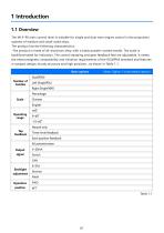
The WLF-90 main control lever is suitable for single and dual main engine control in the propulsion systems of medium and small-sized ships. The product has the following characteristics: -The product is made of all-aluminum alloy, with a black powder-coated handle. The scale is backilluminated for indication. The control damping and gear feedback feel are adjustable. It meets the electromagnetic compatibility and vibration requirements of the IEC60945 standard and features a compact design, sturdy structure and high precision., as shown in Table 1.1. Basic options (Note: Option 1 is the default...
Open the catalog to page 4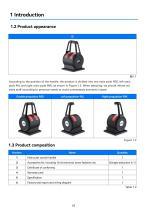
According to the position of the handle, the product is divided into two main push 90D, left main push 90L and right main push 90R, as shown in Figure 1.2. When selecting, we should inform our sales staff according to personal needs to avoid unnecessary economic losses!
Open the catalog to page 5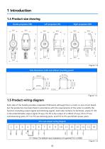
Each side of the handle provides a separate PCB board, although this is a multi-in-one circuit board, but the production has been fixed in accordance with the requirements of the order to solidify the function (including output signal and dimming signal), each side contains 16 terminals, where P1~P3 is the potentiometer output signal (if any), P4~P5 is the output of 4~20mA (if any), P6 to P7 are commissioning ports, P11 to P12 are dimming ports, and P13 to P14 are DC24V power ports.
Open the catalog to page 6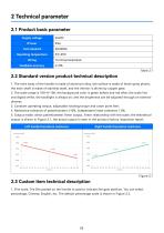
1. The main body of the handle is made of aluminum alloy, the surface is made of black spray plastic, the main shaft is made of stainless steel, and the interior is driven by copper gear; 2. The scale range is 100~0~100, the background color is green before and red after, the scale line and digital white, the backlight is always on, and the brightness can be adjusted through an external dimmer; 3. Constant operating torque, adjustable rotating torque and caton point feel; 4. Resistance tolerance of potentiometer ±10%, independent linear tolerance 1.0%; 5. Output mode: direct potentiometer linear...
Open the catalog to page 8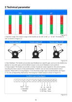
2. Rotation range: The rotation range of the handle can be ±60°, 0~60°, or -15~60°. The default is ±60°, as shown in Figure 2.3. lout+ lout-
Open the catalog to page 9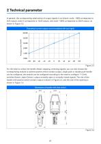
In general, the corresponding relationship of output signals is as follows: scale -100% corresponds to 4mA output, scale 0 corresponds to 12mA output, and scale +100% corresponds to 20mA output, as shown in Figure 2.5. For the need to collect the handle ahead, stopping, reversing signals, you can also choose the corresponding module to achieve passive switch contact output, single push or double push handle can be configured, the module can be configured according to the need to configure 1~3 limit switches (brand: Japan Omron), output normally open or normally closed signals. The size of the...
Open the catalog to page 10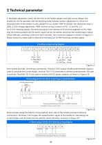
4 to 20mA output wiring diagram Each handle provides 16 terminal connections. Terminal 1/2/3 output handle potentiometer signal is used to calculate the current Angle; Terminal 10/11/12 connected to dimmer potentiometer, this part is optional; Terminals 13/14 are used to connect 24V DC power supplies, as shown in Figure 2.8. Some handles adopt the bottom wiring method. Each side of the handle provides 8 terminal connections. Terminals 1/2/3 output the potentiometer signal of the handle for calculating the current Angle, and terminals 5/6 are used for direct dimming, as shown in Figure 2.9
Open the catalog to page 11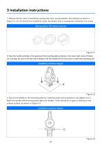
Spring washers, flat washers and nuts 2. Place the handle vertically in the opening of the mounting plate as shown in the lower right corner of Figure 3.2, and align the screw with the hole B. Rotate or tilt the handle into the hole when it meets the protruding part.
Open the catalog to page 12
4. After the handle is installed on the mounting plate, Figure 2.5 shows the electrical cables. After the wiring is completed, it should be confirmed that the external wiring is firm and reliable. 5. Check the external cables, which should be connected normally; The backlight should emit light normally; Push the handle lever, the switch can complete the normal on-off action. After commissioning, disconnect the power supply.
Open the catalog to page 13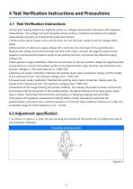
4.1 Test Verification Instructions Control lever testing adopts two methods: power-on voltage measurement and power-off resistance measurement. The voltage test best simulates actual working conditions and delivers the highest measurement accuracy, so it shall be the preferred method. 1. Verify normal power supply to the control lever, and set the multi-meter to the DC voltage (VDC) range. 2. Measurement of reference supply voltage Ufs: Locate the two terminals of the potentiometer. Measure the voltage across the terminals with the multi-meter; connect the negative probe to the negative terminal...
Open the catalog to page 14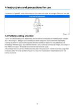
1. If it is not used according to the requirements, the loss shall be borne by the user; Rated backlight voltage 2 24V. If the backlight is damaged due to exceeding the rated voltage, the user shall bear the responsibility. 2. During use, when the output in the propulsion direction exceeds the range of 0 ~ 5KQ, please stop use immediately; When the output value between terminals 1 and 2 cannot be continuously changed, stop using it in time. Method of stopping the service: Disconnect the external power supply. 3. According to the characteristics of the accessories used in this product, the instantaneous...
Open the catalog to page 15
This product has been put into operation since the use, basically no fault, with our statistics, the after-sales problem is basically due to wiring errors, resulting in normal use, in addition, there is no technical fault. Customers in the use of the process, if you find technical problems, please promptly communicate with our technical personnel. (Note: Each handle has a unique factory number)
Open the catalog to page 16All Ningbo Shanbei Technology Co.,Ltd catalogs and brochures
- Analog indicator
- Steering compass
- Shanbei Technology engine control lever
- Boat steering compass
- Ship sensor
- Boat control lever
- Shanbei Technology digital control lever
- Built-in steering compass
- Mechanical control lever
- Shanbei Technology single-lever control lever
- Multi-lever control lever
- Digital indicator
- Shanbei Technology surface-mount control lever
- Shanbei Technology ship control lever
- Ship indicator
- Motor indicator
- Ship joystick
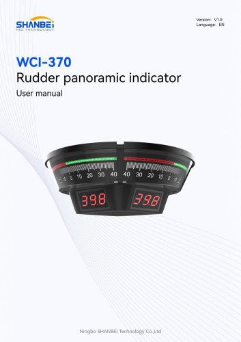
- Rudder angle indicator
- Multi-function joystick