
- Catalogs
- Ningbo Shanbei Technology Co.,Ltd
- WLF-72_Azimuth control lever_User manual_EN_V1.3

WLF-72_Azimuth control lever_User manual_EN_V1.3
1 /20Pages
WLF-72_Azimuth control lever_User manual_EN_V1.3
1 /20Pages
Catalog excerpts

User manual Ningbo SHANBEI Technology Co.,Ltd
Open the catalog to page 1
Warning: Before using this product, please refer to the important safety information in the user manual and review all warnings, limitations and disclaimers. This product is no substitute for proper training and careful seamanship. Proper installation and proper use of the equipment is the responsibility of the owner to avoid accidents, personal injury or property damage. The user of this product is solely responsible for compliance with maritime safety practices. The owner is solely responsible for installing and using the equipment in a manner that will not cause accidents, personal injury...
Open the catalog to page 2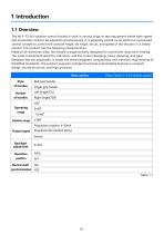
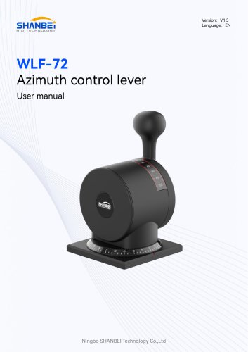
The WLF-72 full-rotation control handle is used in various ships or test equipment where both speed and orientation need to be adjusted simultaneously. It is generally placed on an electrical centralized control console to control the azimuth Angle, tilt Angle, thrust, and speed of the thruster in a linked manner. The product has the following characteristics: Made of all-aluminum alloy, the handle is ergonomically designed for convenient long-term holding. The scale is backilluminated for indication, and the control damping, rotary damping, and gear feedback feel are adjustable. It meets the...
Open the catalog to page 4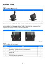
Products are divided into left paddle handle and right paddle handle according to the position of the handle, as shown in Figure 1.2. When selecting, we should inform our sales staff according to personal needs to avoid unnecessary economic losses! If the contract does not specify the style required by the customer, we default to the right paddle handle.
Open the catalog to page 5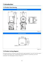
The product provides 16 terminals, using DC24 power supply separately, Y axis and Z axis each output 1 4~20mA current signal, with 1 potentiometer dimming interface (if not dimming, can not be connected). The wiring diagram is shown in Figure 1.5.
Open the catalog to page 6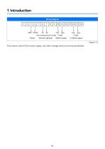
Power Dimmer optional ~20mA output lout- lout+ Z-axis Wiring diagram The product uses DC24V power supply, and other voltage levels are strictly prohibited.
Open the catalog to page 7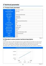
(1) The scale range is 0~100, the background color is green before and red after, the scale line and digital white, the backlight is adjustable, and the brightness is adjusted by the circuit board knob; (2) Constant operating torque, adjustable rotating torque and caton point feel, good feel; (3) Output mode: 4~20mA current output, linear relationship with the scale, as shown in Figure 2.1. Y-axis theoretical current output curve
Open the catalog to page 8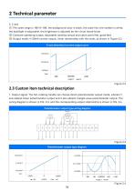
(1) The scale range is 180~0~180, the background color is black, the scale line, the number is white, the backlight is adjustable, the brightness is adjusted by the circuit board knob; (2) Constant operating torque, adjustable rotating torque and caton point feel, good feel; (3) Output mode: 4~20mA current output, linear relationship with the scale, as shown in Figure 2.2. 1. Output signal: The full-rotating handle can choose direct potentiometer output mode, wherein Y axis adopts linear potentiometer output and Z axis adopts triangle wave potentiometer output. The wiring diagram is shown in...
Open the catalog to page 9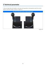
2. Stern driving: When the handle is in the stern driving position, the propulsion scale film and the rotation scale film change, as shown in Figure 2.5:
Open the catalog to page 10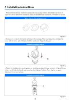
1. Remove the four sets of installation accessories (nuts, spring washers, flat washers), as shown in Figure 3.1. Do not remove the installation studs. Set aside 4 sets of accessories, remember not to lose. 2. As shown in 3.2, place the handle vertically in the opening of the mounting plate, and align the screw with the screw hole B. Rotate or tilt the handle into the protruding part. 3. Fasten the handle to the mounting plate by installing studs and fittings, as shown in Figure 3.3, and tighten nut C. Make the handle and mounting plate tight and reliable. There shall be no gap or shaking on...
Open the catalog to page 11
4. Install the handle to the mounting plate and connect electrical cables. After the wiring is completed, it should be confirmed that the external wiring is firm and reliable. 5. Check the external cables, which should be connected normally; The backlight should emit light normally; Push the handle, the switch can complete the normal on-off action. After commissioning, disconnect the power supply.
Open the catalog to page 12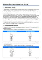
1. The initial position of the operation handle pointer (including the direction of propulsion and rotation) is in the middle (0 scale). At this time, the output value of the advance direction (the reading of the identification numbers 10 and 11) is 12mA± 1 %; The output value corresponding to the direction of rotation (reading numbers 14 and 15) is 12mA± 1%. 2. Switch on the power supply, connect the cable as shown in Figure 1.5, push the handle lever, and the resistance reading between the identification number 10 and 11 is the output value of continuous linear change from 4 to 20mA. The red...
Open the catalog to page 13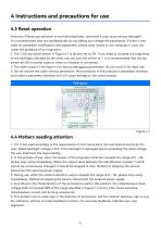
Attention (Please pay attention to the following items, otherwise it may cause serious damage!) : It is recommended that non-professionals do not debug and change the parameters. If there is any need for parameter modification and adjustment, please send it back to our company or carry out under the guidance of our engineers. 1. The 1-bit dip switch shown in Figure 4.1 is factory set at ON. If you need to increase the brightness of the backlight indicated by the scale, you can turn the switch to 1. It is recommended that the dip switch be ON in normal cases or when no rheostat is connected. 2....
Open the catalog to page 14
This product has been put into operation since the use, basically no fault, with our statistics, the after-sales problem is basically due to wiring errors, resulting in normal use, in addition, there is no technical fault. Customers in the use of the process, if you find technical problems, please promptly communicate with our technical personnel. (Note: Each handle has a unique factory number)
Open the catalog to page 15
6.1 Safety protection devices and precautions 1. In the important position of this product, the fastening seals have been processed before leaving the factory, and shall not be disassembled without permission. If the seals are damaged, any product quality problems will be borne by the buyer. 2. The damping part used in this product is a loss part, the warranty period is 1 year, effective from the date of delivery; During the warranty period, damping changes, which can not be used normally or seriously affect the operation, shall be maintained by us free of charge. If damping changes occur outside...
Open the catalog to page 16All Ningbo Shanbei Technology Co.,Ltd catalogs and brochures


- Analog indicator
- Shanbei Technology control lever
- Steering compass
- Shanbei Technology engine control lever
- Boat steering compass
- Ship sensor
- Boat control lever
- Shanbei Technology digital control lever
- Built-in steering compass
- Mechanical control lever
- Shanbei Technology single-lever control lever
- Multi-lever control lever
- Digital indicator
- Shanbei Technology surface-mount control lever
- Shanbei Technology ship control lever
- Ship indicator
- Motor indicator
- Ship joystick
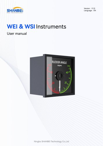
- Rudder angle indicator
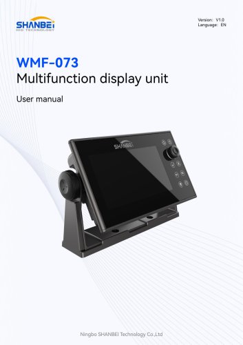
- Multi-function joystick