
- Catalogs
- Ningbo Shanbei Technology Co.,Ltd
- WLF-40_Mini rudder control lever_User manual_EN_V1.0

WLF-40_Mini rudder control lever_User manual_EN_V1.0
1 /20Pages
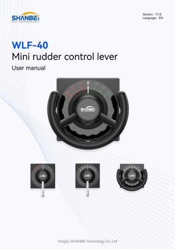
WLF-40_Mini rudder control lever_User manual_EN_V1.0
1 /20Pages
Catalog excerpts

User manual Ningbo SHANBEI Technology Co.,Ltd
Open the catalog to page 1
Warning: Before using this product, please refer to the important safety information in the user manual and review all warnings, limitations and disclaimers. This product is no substitute for proper training and careful seamanship. Proper installation and proper use of the equipment is the responsibility of the owner to avoid accidents, personal injury or property damage. The user of this product is solely responsible for compliance with maritime safety practices. The owner is solely responsible for installing and using the equipment in a manner that will not cause accidents, personal injury...
Open the catalog to page 2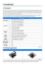
The WLF-40 mini rudder control lever is used for the servo control of the ship's steering system. It can send out rudder command values and is equipped with a potentiometer and a dial. Features include: -Aluminum alloy housing, standard 5KQ potentiometer output, damping feel; adjustable backlight for the scale; customizable scale and rotation angle. The basic customization items of the product include the following categories, as shown in Table 1.1. Other customization items will be agreed upon separately during the order process. Basic options (Note: Option 1 is the default option) The product...
Open the catalog to page 4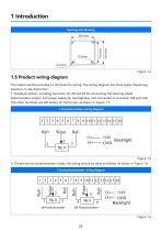
1.5 Product wiring diagram The output section provides 16 terminals for wiring. The wiring diagram has three types. Please pay attention to the distinction: 1. Standard version, including terminals 1#, 2# and 3# for connecting the steering wheel potentiometer output, 24V power supply for backlighting, and connected to terminals 13# and 14#. The other terminals are left empty for future use, as shown in Figure 1.5. 1 Standard version wiring diagram 2. If there are two potentiometers inside, the wiring should be done as follows, as shown in Figure 1.6. 2 Dual potentiometer wiring diagram
Open the catalog to page 6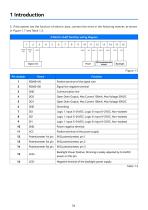
3. If the system has the function of electric axes, connect the wires in the following manner, as shown in Figure 1.7 and Table 1.3.
Open the catalog to page 7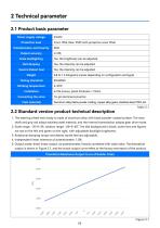
1. The steering wheel main body is made of aluminum alloy with black powder-coated surface. The main shaft and grip rod adopt stainless steel material, and the internal transmission adopts gear drive mode. 2. Scale range: -35~0~35; rotation range: -60~0~60°. The dial background is black; scale lines and figures are red on the left and green on the right, with adjustable backlight brightness. 3. Rotational damping torque and detent tactile feel are adjustable. 4. Independent linear tolerance of potentiometer: 1.0%. 5. Output mode: direct linear output via potentiometer, linearly correlated with...
Open the catalog to page 8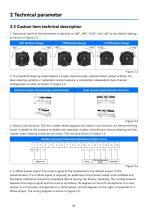
1. Rotational travel of the handwheel is optional at ±60°, ±90°, ±140°, with ±60° as the default setting, as shown in Figure 2.2. 2. The standard steering wheel adopts a single-channel single-potentiometer output scheme. For dual-steering systems or redundant control systems, a completely independent dual-channel configuration is used, as shown in Figure 2.3. 3. Electric axis function: The mini rudder wheel supports the electric axis function. An internal driving motor is added to the product to enable two operation modes: conventional manual steering and the rudder wheel rotating driven by the...
Open the catalog to page 9
This product supports one-hand operation. The operating instructions are as follows: 1) Clockwise rotation of the grip: The steering wheel outputs a starboard steering signal. The larger the rotation angle, the greater the starboard steering amplitude. The maximum rotation angle shall not exceed the configured rotational travel (standard ±60°). 2) Counterclockwise rotation of the grip: The steering wheel outputs a port steering signal. The larger the rotation angle, the greater the port steering amplitude. The maximum rotation angle shall not exceed the configured rotational travel. 3) Return-to-center...
Open the catalog to page 10
4) This product can be remotely operated through the signal line (RS485 bus). The operation method is as follows: © RS485 remote position control © High-precision steering command control © 1-channel 5KQ potentiometer analog output © 0-24V continuous backlight dimming The backlight supports dimming function. The adjustment method is achieved by using an external 0-24V power supply dimming device to adjust the backlight brightness, which is suitable for different nighttime operating environments. 1) Signal Calibration: After installation, connect the 1 st to 3rd pins of the potentiometer to the...
Open the catalog to page 11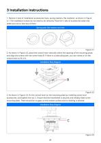
3. As shown in Figure 3.3, fix the control lever on the mounting plate by installing screws and accessories, and tighten the nut C. Ensure that the handwheel is securely and reliably fixed to the mounting plate. There should be no gaps on the contact surface and no shaking is allowed.
Open the catalog to page 12
4. After installing the control lever onto the mounting plate, proceed with the electrical wiring. After the wiring is completed, it is necessary to confirm that the externa! wiring is firmly and reliably connected. 5. Test the external wiring; it should be properly connected; the backlight should be functioning normally; when turning the handwheel, the switch should be able to perform the normal on-off operation. After the debugging is completed, disconnect the power supply.
Open the catalog to page 13
1. The initial position of the control lever pointer is at the center (0 mark), and at this point, the resistance value of the potentiometer (readings of identification numbers 4 and 5) is 2.5KQ ± 10%. 2. Connect the power supply, follow the wiring shown in Figure 1.5, adjust the dimming knob, and the brightness of the backlight will change. Turning the steering wheel clockwise or counterclockwise, the resistance reading between identification numbers 4 and 5 will change linearly from 0 to 5KQ continuously. After completion, place the steering wheel at the 0 mark. 3. When operating the steering...
Open the catalog to page 14
This product has been put into operation since the use, basically no fault, with our statistics, the after-sales problem is basically due to wiring errors, resulting in normal use, in addition, there is no technical fault. Customers in the use of the process, if you find technical problems, please promptly communicate with our technical personnel. (Note: Each handle has a unique factory number)
Open the catalog to page 15All Ningbo Shanbei Technology Co.,Ltd catalogs and brochures







- Analog indicator
- Steering compass
- Shanbei Technology engine control lever
- Boat steering compass
- Ship sensor
- Boat control lever
- Shanbei Technology digital control lever
- Built-in steering compass
- Mechanical control lever
- Shanbei Technology single-lever control lever
- Multi-lever control lever
- Digital indicator
- Shanbei Technology surface-mount control lever
- Shanbei Technology ship control lever
- Ship indicator
- Motor indicator
- Ship joystick
- Rudder angle indicator
- Multi-function joystick