
- Catalogs
- Ningbo Shanbei Technology Co.,Ltd
- WFU-500_Follow-up Steering Control System_EN_1.0

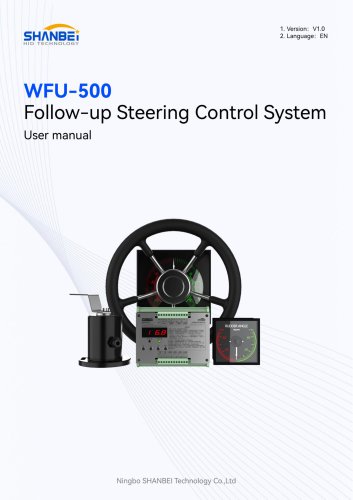
WFU-500_Follow-up Steering Control System_EN_1.0
1 /25Pages
WFU-500_Follow-up Steering Control System_EN_1.0
1 /25Pages
Catalog excerpts

User manual Ningbo SHANBEI Technology Co.,Ltd
Open the catalog to page 1
Warning: Before using this product, please refer to the important safety information in the user manual and review all warnings, limitations and disclaimers. This product is no substitute for proper training and careful seamanship. Proper installation and proper use of the equipment is the responsibility of the owner to avoid accidents, personal injury or property damage. The user of this product is solely responsible for compliance with maritime safety practices. The owner is solely responsible for installing and using the equipment in a manner that will not cause accidents, personal injury...
Open the catalog to page 2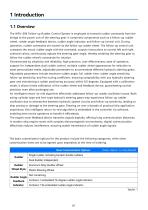
The WFU-500 Follow-up Rudder Control System is employed to transmit rudder commands from the bridge to the power unit of the steering gear. It comprises components such as a follow-up rudder wheel, rudder angle feedback device, rudder angle indicator, and follow-up control unit. During operation, rudder commands are issued via the follow-up rudder wheel. The follow-up control unit compares the actual rudder angle with the command, outputs instructions to control left and right solenoid valves, continuously adjusts the steering gear angle, thereby enabling the steering gear to follow the rudder...
Open the catalog to page 4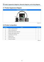
2 Product appearance diagrams, dimension diagrams, and wiring diagrams
Open the catalog to page 5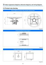
2 Product appearance diagrams, dimension diagrams, and wiring diagrams Rudder Angle Indicator Outline Dimension Diagram
Open the catalog to page 6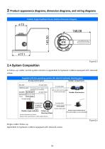
2 Product appearance diagrams, dimension diagrams, and wiring diagrams 2.4 System Composition si-follow-up rudder control system solution is applicable to hydraulic rudders equipped with solenoid valves.Supplied with the operating system (for electric hydraulic steering gear) driving control panel Rudder compartment Battery pack The backup power supply is not required to be connected Direct Current Power Supply Rudder Angle Signal Rudder Angle Indicator Follow-up Steering Wheel Can be connected to a dimmer Optional other specifications rudder angle indicator Left and right electromagne Switch...
Open the catalog to page 7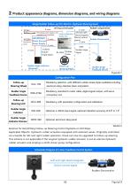
driving control panel Battery pack The backup power supply is not required to be connected Follow-up Operation Rudder Unit AC/DC24V Direct Current Power Supply Left and right electromagnets Switch control Rudder Electrovalve 4~20mA Rudder Angle Signal Rudder Angle Signal Rudder Angle Indicator Follow-up Rudder Angle Feedback Device Solution for Retrofitting Follow-up Steering Control Systems on Old Ships Applicable Objects: Hydraulic rudder actuators equipped with solenoid valves. Originally controlled via a handle for left and right rudder operation, these can now be upgraded to follow-up steering....
Open the catalog to page 8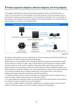
As illustrated, the traditional simple steering method employs a handle or handwheel switch to control the on/off state of an electromagnetic valve. When steering, continuous pressure must be maintained; if released, the electromagnetic valve immediately de-energizes. This not only leads to easy damage of the handle but also causes fatigue for the steering operator. The modified follow-up steering system is as shown in the following figure: Schematic Diagram of Follow-up Steering Principle for Old Ship Reconstruction Left and right electromagnets Switch control signal' Rudder Electrovalve Pattern...
Open the catalog to page 9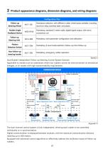
Dual Rudder Independent Follow-up Steering Control System Solution Applicable to vessels such as catamarans where two rudders cannot be interconnected via mechanical linkages, or to vessels with high maneuverability requirements. Direct Current Power Supply Rudder compartment Rudder Angle Indicator 2-core 4~20mA Rudder Angle Signal 2-core 4~20mA Rudder Angle Signal Switch control signal Servo Operation Unit Servo Operation Unit Rudder Angle Signal Rudder Angl< Signal Switch control signal Rudder compartment Rudder Angle Feedback Device Rudder Angle Electrovalve Feedback Device* The dual-channel...
Open the catalog to page 10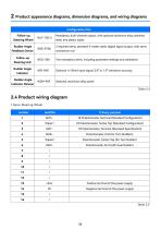
2 Product appearance diagrams, dimension diagrams, and wiring diagrams
Open the catalog to page 11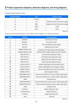
2.Rudder Angle Feedback Device
Open the catalog to page 12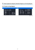
2 Product appearance diagrams, dimension diagrams, and wiring diagrams
Open the catalog to page 13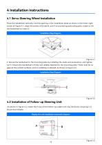
Place the handwheel vertically into the opening in the installation plate as shown in the lower-right corner of Figure 4.1, align the screws with hole B, and if encountering protruding parts, rotate or tilt the handwheel to insert it. Installation Step Diagram As shown in Figure 4.3, install the A clip of the follow-up rudder unit into the B slot, ensuring it is secure and reliable.
Open the catalog to page 15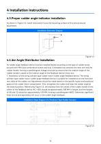
As shown in Figure 4.4, install instrument A onto the mounting surface of B to ensure secure attachment. he rudder angle feedback device must be installed flexibly according to the type of rudder motor, secured with M8 triple combination screws and nuts. A threaded rod connects the lever arm and the rudder handle, forming a parallelogram linkage structure to ensure that the rotation angle of the rudder handle is equal to the rotation angle of the feedback device's lever arm. 1. Installation of the swing cylinder type rudder motor rudder angle feedback device: The swing cylinder type rudder motor...
Open the catalog to page 16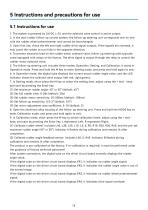
1. The system is powered by 24VDC ± 2V, and the solenoid valve control is active output; 2. In the dual rudder follow-up control system, the follow-up steering unit corresponds one-to-one with the rudder wheel potentiometer and cannot be interchanged; 3. Upon first use, check the left and right rudder drive signal outputs. If the signals are reversed, it may cause the rudder to turn fully in the opposite direction; 4. To prevent excessive load on the rudder motor solenoid valve, follow-up steering units typically come equipped with relays at the factory. The drive signal is output through the...
Open the catalog to page 18
value normally; 2. If the digital tube on the drive circuit board displays ER1, it indicates that there is no rudder angle signal; 3. If the digital tube on the drive circuit board displays ER2, it indicates that the rudder angle value is out of the normal range; 4. If the digital tube on the drive circuit board displays ER3, it indicates that there is no signal from the rudder wheel potentiometer.
Open the catalog to page 19All Ningbo Shanbei Technology Co.,Ltd catalogs and brochures


- Analog indicator
- Shanbei Technology control lever
- Steering compass
- Shanbei Technology engine control lever
- Boat steering compass
- Ship sensor
- Boat control lever
- Shanbei Technology digital control lever
- Built-in steering compass
- Mechanical control lever
- Shanbei Technology single-lever control lever
- Multi-lever control lever
- Digital indicator
- Shanbei Technology surface-mount control lever
- Shanbei Technology ship control lever
- Ship indicator
- Motor indicator
- Ship joystick
- Multi-function joystick