
- Catalogs
- Ningbo Shanbei Technology Co.,Ltd
- WCI-370_Rudder panoramic indicator_User manual_EN_V1.0

WCI-370_Rudder panoramic indicator_User manual_EN_V1.0
1 /15Pages
WCI-370_Rudder panoramic indicator_User manual_EN_V1.0
1 /15Pages
Catalog excerpts
User manual Ningbo SHANBEI Technology Co.,Ltd
Open the catalog to page 1
Warning: Before using this product, please refer to the important safety information in the user manual and review all warnings, limitations and disclaimers. This product is no substitute for proper training and careful seamanship. Proper installation and proper use of the equipment is the responsibility of the owner to avoid accidents, personal injury or property damage. The user of this product is solely responsible for compliance with maritime safety practices. The owner is solely responsible for installing and using the equipment in a manner that will not cause accidents, personal injury...
Open the catalog to page 2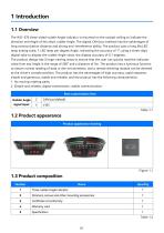
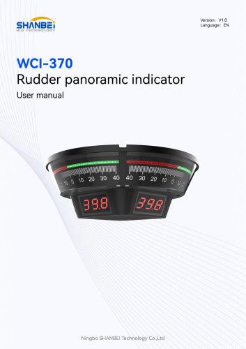
The WC1-370 three-sided rudder Angle indicator is mounted on the cockpit ceiling to indicate the direction and Angle of the ship's rudder Angle. The digital CAN bus interface has the advantages of long communication distance and strong anti-interference ability. The product uses a long life,LED lamp analog scale, 1 LED lamp per degree Angle, indicating the accuracy of 1°, using a three-digit digital tube to display the rudder Angle value, the display accuracy of 0.1 degrees. The product design has 3 large viewing areas to ensure that the user can quickly read the indicator value from any Angle...
Open the catalog to page 4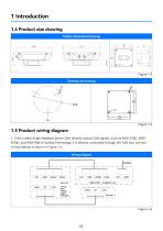
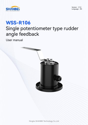
1.5 Product wiring diagram 1. If the rudder Angle feedback device CAN directly output CAN signals, such as WSS-270C, WSS-R106C and WSS-R68 of Scallop Technology, it is directly connected through the CAN bus, and the wiring method is shown in Figure 1.4.
Open the catalog to page 5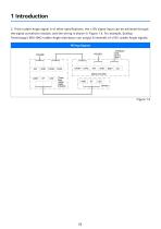
2. If the rudder Angle signal is of other specifications, the ±1OV signal input can be achieved through the signal conversion module, and the wiring is shown in Figure 1.5. For example, Scallop Technology's WDI-8AO rudder Angle distributor can output 8 channels of±10V rudder Angle signals.
Open the catalog to page 6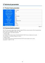
WCI-370 three-plane rudder Angle indicator adopts CAN bus communication: 29-bit extended data frame, frame ID: 0x02099827; Baud rate: 100K; The rudder Angle is calculated as follows: For example, CAN receives data: 01 02 03 04 05 06 07 08. The last six bytes are not used The calculation is as follows: (256+6) *0.1=26.2° For example, CAN receives FE 98 03 04 05 06 07 08. The last six bytes are not used Calculation: (-360) *0.1=-36°
Open the catalog to page 7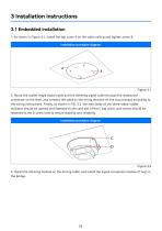
2. Route the rudder Angle signal cable and the dimming signal cable through the waterproof connector on the shell, and connect the cable to the wiring terminal on the circuit board according to the wiring instructions. Finally, as shown in FIG. 3.2, the main body of the three-sided rudder indicator should be upward and fastened to the card slot of the C top cover, and screws should be fastened to the D screw hole to ensure stability and reliability. 3. Install the dimming module on the driving table, and install the signal conversion module (if any) in the bridge.
Open the catalog to page 8
1. Identify the content of the indicating area to obtain parameters, one is scale display, the other is digital display. 2. Adjust the brightness of the display area by rotating the dimmer.
Open the catalog to page 9
This product has been put into operation since the use, basically no fault, with our statistics, the after-sales problem is basically due to wiring errors, resulting in normal use, in addition, there is no technical fault. Customers in the use of the process, if you find technical problems, please promptly communicate with our technical personnel.
Open the catalog to page 10
6.1 Safety protection devices and precautions 1. In the important position of this product, the fastening seals have been processed before leaving the factory, and shall not be disassembled without permission. If the seals are damaged, any product quality problems will be borne by the buyer. 2. Once the product fails to operate normally, please stop using and disconnect the power supply immediately, and contact our after-sales service engineer for a solution. 6.2 Troubleshooting procedures and methods 1. In the process of use, there is an unsolvable fault problem, contact our after-sales service...
Open the catalog to page 11
7.1 Daily maintenance and maintenance In the daily non-use state, attention should be paid to the maintenance of this product. Through maintenance, maintenance can improve the service fife of the product, the specific maintenance and maintenance methods are as follows: 1. Wipe the surface of the product regularly with a dry rag to ensure that the outside of the product is clean and tidy. 1. Please stop using the device when data problems occur. Contact our after-sales engineer. 2. The input voltage shall be carried out in strict accordance with the wiring instructions. Failure to operate according...
Open the catalog to page 12
Physical damage to the product caused by violent shaking and collision should be avoided during transportation. Room temperature, dry, cool environment. The warranty period of this product is 12 months from the date of receipt of the goods by the buyer. Based on the date of receipt of documents for express delivery or the date of receipt of invoice.
Open the catalog to page 13
9.1 Phone number of the after-sales engineer Manufacturer: Ningbo SHANBEI Technology Co., LTD Address: A2-902, R&D Park, High-tech Zone, Ningbo Postal Code: 310001 Tel: (0574) 87182781 Fax: (0574) 87182781
Open the catalog to page 14
For more information, please visit:Ningbo Shanbei Technology Co.,Ltd Address: 902 Area A, R&D Park, High-tech Zone, Ningbo, Zhejiang, China WhatsAPP: +86 13186888051 E-mail: [email protected] Wechat: 13186888051
Open the catalog to page 15All Ningbo Shanbei Technology Co.,Ltd catalogs and brochures
- Analog indicator
- Shanbei Technology control lever
- Steering compass
- Shanbei Technology engine control lever
- Boat steering compass
- Ship sensor
- Boat control lever
- Shanbei Technology digital control lever
- Built-in steering compass
- Mechanical control lever
- Shanbei Technology single-lever control lever
- Multi-lever control lever
- Digital indicator
- Shanbei Technology surface-mount control lever
- Shanbei Technology ship control lever
- Ship indicator
- Motor indicator
- Ship joystick
- Multi-function joystick