- Catalogs
- MBC MARINE - MARINE AIR CONDITONS SOLUTIONS
- MBC Marine User Manual for ESC SCP modells
- Company
- Products
- Catalogs
- News & Trends
- Exhibitions
MBC Marine User Manual for ESC SCP modells
1 /41Pages

MBC Marine User Manual for ESC SCP modells
1 /41Pages
Catalog excerpts

INSTALLATION AND USER MANUAL FOR-SSC-ESC-SCP UNITS
Open the catalog to page 1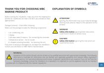
THANK YOU FOR CHOOSING MBC MARINE PRODUCT! Before starting the installation, make sure that the shipping box and the air conditioner are intact. DO NOT use a broken or damaged product. Package Contents – Check After Unboxing Make sure the package includes the following components: • 1 LAN data cable (5 meters) – for connecting the controller 1 temperature sensor – for AI1 socket 4 L-shaped mounting brackets – for securing the unit If any item is missing or damaged, do not begin the installation – contact your distributor or MBC Marine representative. ATTENTION!! Ignoring this information may...
Open the catalog to page 3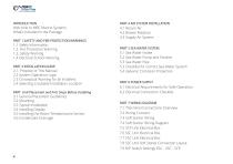
Welcome to MBC Marine Systems What's Included in the Package PART 1 SAFETY AND FIRE PROTECTION WARNINGS 1.2. Fire Protection Warning 1.4 Electrical Schock Warning PART 2 INSTALLATION GUIDE 2.1. Propose of This Manual 2.2 System Operation Logic 2.3 Conceptual Warning for all Installers 2.4 Selecting a Suitable Installation Location PART Unit Placement and First Steps Before Installing 3.1 General Placement Guidelines 3.5 Installing the Room Temeperature Sensor PART 4 AIR SYSTEM INSTALLATION PART 5 SEA WATER SYSTEM 5.2 Sea Water Pump and Strainer 5.3 Checklist for Correct Sea Water System 5.4 Galvanic...
Open the catalog to page 4
PART 12 KEY INSTALLATION NOTES PART 13 LEGAL DISCLAMERS AND LIABILITY 9.1 Understandig Error Codes 9.2 ERROR 1 Room Temperature Sensor Error 9.3 ERROR 2 Evaporator Temperature Error 9.3 ERROR 3 Condenser Temperature Error 9.4 ERROR 4 Overheated Evaporatot Protection 9.5 ERROR 5 Refrigerant Leak Mailfunction 9.6 ERROR 6 ompressor Overheating 9.8 ERROR 8 High Gas Temperature Error 9.9 ERROR 9 Evaporatot Temperature Protection (DEFROSTING) 9.10 ERROR 10 Sea Water Temperature Protection 9.11 ERROR 11 Incorrect Connection 9.12 ERROR 12 Compressor Overcurrent Error 9.15 ERROR 15 Communication Failture...
Open the catalog to page 5
PART 1. SAFETY AND FIRE PROTECTION WARNINGS 1.1 SAFETY INFORMATION: The manufacturer assumes no liability for damage to the device in the following cases: • Installation or connection failure • Damage to the product due to mechanical impact and over voltage • Modification of the product without the express written permission of the manufacturer • Unusual use, differing from standards 1.2 FIRE PROTECTION WARNING: Installation and maintenance of the unit may be dangerous due to pressurized copper pipes and electrical equipment. When working on the unit, always take the safety precautions into account...
Open the catalog to page 6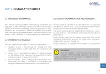
PART 2. INSTALLATION GUIDE 2.1 PURPOSE OF THIS MANUAL 2.3 CONCEPTUAL WARNING FOR ALL INSTALLERS: This manual provides guidance for the proper installation and operation of MBC Marine ESC series 230V self-contained direct expansion marine air conditioning systems. Its purpose is to offer installers and maintenance personnel detailed, step-by-step, clear, and practical support throughout the entire lifecycle of the system – from installation to troubleshooting and maintenance. No two boats or installations are the same. Do not copy the installation of another boat – the correct setup is determined...
Open the catalog to page 7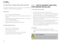
2.4 SELECTING A SUITABLE INSTALLATION LOCATION Choosing the right placement for the system is critical. Before the installation consider the following guidelines: • A dry, well-ventilated enclosed space • Minimum 60 mm clearance from surrounding furniture (on all sides) • A stable, level surface, preferably with a slight 1-2 cm slope to allow condensate drainage • Easily accessible for maintenance • Isolated from heat sources and exhaust gases Avoid the Following Locations: • Engine room or machinery space • Directly next to ventilation ducts • Wet or damp floor areas • In the path of exhaust...
Open the catalog to page 8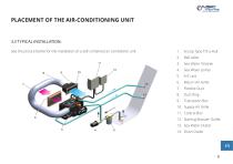
PLACEMENT OF THE AIR-CONDITIONING UNIT 3.3 TYPICAL INSTALLATION: See the picture below for the installation of a self-contained air conditioner unit. 1. Scoop Type Thru-Hull 12. Starting Booster Outlet
Open the catalog to page 9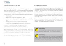
3.4 INSTALLING DISPLAY (CD-3 Type) Before installing the display, observe the following guidelines: Install the control panel only on a surface located higher than the centerline of the cabin, in a location protected from both external and internal sources of heat and light. Do not install the display in locations where it may be exposed to: • Direct sunlight • Nearby heat-producing appliances or devic • Partition walls with potential heat accumulation behind the panel • Directly above or below air intake or outlet vents • Ensure that the display is easily accessible for operation Although the...
Open the catalog to page 10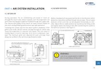
PART 4. AIR SYSTEM INSTALLATION 4.1. RETURN AIR During operation, the air conditioning unit draws in room air through the return side, where it passes over the evaporator coil and is then discharged cooled (or heated) through the supply side. The volume and quality of the return air have a direct impact on the unit’s cooling/heating performance and safe operation. Before installation (if necessary) set the fan in the direction which allows the most direct airflow through the air pipes. The air outlet direction of the unit’s fan can be adjusted horizontally or vertically. Adjust the air outlet...
Open the catalog to page 11
Supply air is the cooled or heated air that enters the cabin after passing through the evaporator. The total duct length should not exceed 4 meters. Avoid 90° or sharp bends, as they can reduce airflow by up to 25%. Supply grilles should always be installed as high as possible in the cabin, since cold air naturally sinks and warm air rises. When adjusting the direction of the grille louvers, make sure the air is not directed toward the return grille, as this can create a short air cycle. Ducts must be installed tightly and without creases, ensuring they are not compressed later by furniture or...
Open the catalog to page 12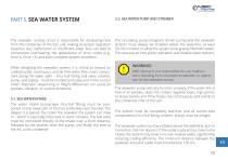
PART 5. SEA WATER SYSTEM 5.2. SEA WATER PUMP AND STRAINER The seawater cooling circuit is responsible for dissipating heat from the condenser of the ESC unit, making its proper operation essential. Any malfunction or insufficient water flow can lead to compressor overheating, the appearance of error codes (e.g., Error 6, Error 12), and even complete system shutdown. The circulating pump (magnetic driven pump) and the seawater strainer must always be installed below the waterline, at least 30–50 cm lower, to allow the system to be gravity-filled with water. This ensures air-free pump operation...
Open the catalog to page 13All MBC MARINE - MARINE AIR CONDITONS SOLUTIONS catalogs and brochures
 MBC Product Catalog 2026
48 Pages
- Boat pump
- Transfer pump
- 12 V pump
- 24 V pump
- Seawater pump
- Boat air conditioner
- Circulation pump
- Boat air vent
- Ships air conditioner
- Stainless steel pump
- Monobloc air conditioner
- Freshwater pump
- Yacht air conditioner
- Stand-alone air conditioner
- 400 V pump
- Yacht pump
- Cooling pump
- Ship fan coil unit
- Yacht air vent
- Split air conditioner