
- Catalogs
- Marlec Engineering
- Rutland 504 e-furl

- Company
- Products
- Catalogs
- News & Trends
- Exhibitions
Rutland 504 e-furl

Rutland 504 e-furl
The Rutland 504 “E-Furl” Windcharger is designed for both land and marine environments, providing a DC power supply to charge 12V battery banks. It features electronic stall regulation for high wind protection, aerodynamic styling for stability, and low wind speed startup for efficient power generation.
- Ensure the mounting pole's diameter does not exceed 38.1mm to prevent damage.
- The turbine must be electrically connected to a regulator or batteries to avoid excessive voltage.
- Stopping the turbine should be done in low wind conditions, and it should be secured properly.
- Handle the generator assembly with care to avoid damage to ceramic magnets.
- Correct polarity must be observed to prevent damage and warranty invalidation.
- The system includes an electronic furling system for high winds, reducing stress on the turbine.
A twelve-step guide is provided for installation, emphasizing the importance of choosing an appropriate site, using the correct mounting pole, and ensuring all electrical connections are secure. The guide also highlights the need for a charge regulator and proper cable specifications.
The Windcharger should be mounted at least 2 meters above the deck on board or 4-6 meters high on land to ensure clear wind flow.
- Batteries and cable specifications are crucial for optimal performance.
- A guideline performance curve is provided to understand expected output.
Regular inspection and maintenance are recommended to ensure longevity. A troubleshooting section is included to address common issues.
The manual includes abbreviated installation instructions in French, Spanish, and German, as well as purchase information and warranty details.
The Rutland 504 “e-Furl” Windcharger installation involves securing the wind generator to a tower and ensuring proper electrical connections. Key steps include running the selected cable down the pole, connecting the wind generator leads to the tower cable using a connector block, and securing connections with insulation tape or a latching plug and socket. The wind generator is then mounted onto the tower using button cap screws and washers.
Follow the wiring systems depicted in Figures 3, 4, and 5, and ensure polarity is observed: red for positive and black for negative. Use appropriate cable sizes as specified in Figure 14 to maintain system performance.
The performance of the wind turbine is highly dependent on its location and height. It should be placed in an area free from obstructions to minimize wind shear and turbulence. The turbine should be mounted at least 2 meters above any deck or obstacles.
Various mounting options are available, including deck mounting for yachts and pivot poles for river boats. The Rutland 504 is designed to fit inside specific tube dimensions, and pivot towers are recommended for ease of installation and maintenance.
Leisure or deep cycle batteries are recommended, with permanent connections to terminals. A charge regulator is advised to prevent overcharging, especially with gel and sealed batteries. Batteries should be connected in parallel to increase ampere hours.
Annual inspections are recommended to ensure system integrity. Routine checks include tightening nuts and bolts, ensuring free rotation of the yaw axis, and checking guy wire tension. Troubleshooting involves static and running tests to verify power output and system functionality.
The performance curve provided is for optimal conditions, and actual performance may vary based on site-specific factors. Regular maintenance and proper siting are crucial for optimal performance.
To ensure the proper functioning of the Rutland 504 “e-Furl” Windcharger, a mechanical inspection may be necessary. This involves checking the brushes and slip ring for wear or damage, and ensuring the hub rotates freely when disconnected from the battery. If issues are identified, contact Marlec or the original vendor for assistance.
The Marlec Engineering Company Limited offers a warranty covering defects in parts and workmanship for 12 months from the purchase date. The warranty includes free replacement of defective parts, provided they are reported promptly and deemed defective by Marlec upon inspection. A valid proof of purchase is required for claims.
Defective parts must be returned prepaid to Marlec Engineering Company Limited or an authorized agent. The warranty is void if there is improper installation, owner neglect, misuse, or damage from flying debris or natural disasters. It does not cover support posts, inverters, batteries, or ancillary equipment not supplied by Marlec.
Marlec assumes no responsibility for incidental or consequential damages, or for damages from unauthorized components. The warranty does not cover non-furling versions of the Rutland Wind charger if a furling device should have been used.
Marlec Engineering Co Ltd, Rutland House, Trevithick Rd, Corby, Northants, NN17 5XY, UK. Tel: +44 (0)1536 201588, Fax: +44 (0)1536 400211, Email: [email protected]
Catalog excerpts

Rutland 504 “e-Furl” Windcharger Rutland 504 “E-Furl” Windcharger (12V) Owners Manual Installation and Operation
Open the catalog to page 1
Rutland 504 "e-Furl" Windcharger Installation and Operation Doc. No: SM-151 Issue A 07/01/2011 2 Marlec Engineering Co Ltd
Open the catalog to page 2
Rutland 504 “e-Furl” Windcharger Contents Introduction
Open the catalog to page 3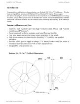
Rutland 504 “e-Furl” Windcharger Introduction Congratulations and thank you for purchasing your Rutland 504 “E-Furl” Windcharger. This has been developed from our successful Rutland 503 and Rutland 504 Marine Windchargers. The utmost of care goes into the manufacture of all our products in our ISO9001 approved factory. To ensure you get the very best out of the Rutland 504 “E-Furl” we recommend that you read this manual and familiarise yourself with its contents before installing and operating the Windcharger system. Summary of Features and Uses • • • • • • Electronic stall regulation provides...
Open the catalog to page 4
Rutland 504 “e-Furl” Windcharger General Guidelines and Warnings • Mounting pole outside diameter MUST NOT exceed 38.1mm for at least the top 0.5m. Larger section poles must not be used as this will reduce the tower to blade clearance. In high wind conditions this could cause damage to the Windcharger by allowing the blade to come into contact with the mounting pole. A broken blade will cause turbine imbalance with consequent damage. When turning, the Windcharger is capable of generating voltages in excess of the nominal voltage. The turbine must never be allowed to rotate unless it is electrically...
Open the catalog to page 5
Rutland 504 “e-Furl” Windcharger Check You Have Received - See Rutland 504 “E-Furl” Exploded View • 1 x in line fuse holder and fuse • 1 x safety turbine with main generator assembly • 1 x nose cone + 3 x snap rivets • 1 x tail fin assembly + 2 x M6 hex head screws • 1 x 5 mm Allen key • 1 x 2-way terminal block • 2 x M8 x 16 button cap screws • 2 x shakeproof washers Exploded View of Rutland 504 “E-Furl” Safety Turbine - The blades incorporating the outer ring must not be tampered with or altered. Nacelle containing Windshaft Assembly Tail Fin Assembly with 2 x M6 x 12 Hex. Head screws, spring...
Open the catalog to page 6
Rutland 504 “e-Furl” Windcharger Assembly & Installation Twelve Step Quick Start Guide 1. Choose an open site to expose the Windcharger to a clear flow of wind and avoiding obstructions. On board mount the Windcharger at least 2.0 metres above the deck and on land at least 4 - 6 m high. Read the full section on Siting. 2. Choose a mounting pole with an internal diameter of 31.7 mm and external diameter of no greater than 38.1 mm for the top 0.5 m minimum to (i) prevent accidental damage and (ii) meet warranty conditions. 3. Mount a charge regulator, from the Marlec range, to a suitable vertical...
Open the catalog to page 7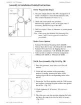
Rutland 504 “e-Furl” Windcharger Assembly & Installation Detailed Instructions Fig 1 Post Adaptor → Tower Preparation (Fig.1) 1. The post adapter fitted to the 504 is designed to fit inside a standard 31.7mm internal diameter tube. Max external diameter 38.1mm (1½”). 2. Mark and centre-punch two positions diametrically opposite, at 90° to the pipe seam if necessary, 40mm from top of the tube. 3. Drill two holes 8.5mm in diameter on centre-punch positions. Note: When using the Rutland 504 Mounting Kits, items 2 and 3 can be ignored, as these are pre-drilled. Marlec Tower Options • • • Rutland...
Open the catalog to page 8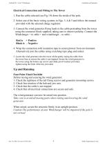
Rutland 504 “e-Furl” Windcharger Electrical Connection and Fitting to The Tower 1. Run the cable selected (see Fig 14) down the inside of the pole. 2. Select one of the basic wiring systems in Figs. 3, 4 & 5 and follow the manual provided with the selected charge regulator. 3. Connect the wind generator flying leads to the cable protruding from the tower using the connector block supplied, taking care to observe polarity. Connect the Windcharger + to cable + and windcharger – to cable – Red is + Positive Black is - Negative 4. Wrap the connection with insulation tape to secure/protect from environment....
Open the catalog to page 9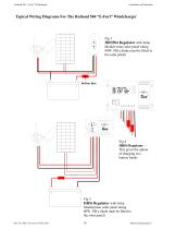
Rutland 504 "e-Furl" Windcharger Typical Wiring Diagrams For The Rutland 504 "E-Furl" Windcharger HRS504 Regulator with Solar Module (max solar panel rating 80W. NB a diode must be fitted to CHARGE REGULATOR HRDi Regulator - This gives the option battery banks HRSi Regulator with Solar Module(max solar panel rating 80W. NB a diode must be fitted to
Open the catalog to page 10
Rutland 504 “e-Furl” Windcharger Siting the Wind charger General Considerations The location and height of the mounting pole or tower for your wind turbine will be the major factor in the overall performance of your system. The smooth flow of wind over land and water is often interrupted by a multitude of obstructions causing wind sheer and turbulence. Wind sheer describes the interference between the fast moving upper air and the slow moving air close to the ground and the resulting decrease in average wind speed as one gets closer to the ground. Turbulence is caused by the wind passing over...
Open the catalog to page 11
Rutland 504 “e-Furl” Windcharger The wind generator should be mounted at a safe height, a minimum of 2 metres (6.5 feet) above the deck and away from other obstacles which could interfere with the blades or tail assembly (Fig. 7). The Rutland 504 is designed to fit inside an aluminium or stainless steel tube with an internal diameter of 31.7mm (11/4”). The external diameter must not exceed 38.1mm (1½”), see Warnings! Suitable tube: 11/2“ 10 SWG aluminium or Stainless Steel 35mm x 1.5mm. The Rutland 504 Mounting Kit is available for deck mounting or short sections of stainless steel tube of 500mm...
Open the catalog to page 12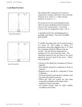
Rutland 504 “e-Furl” Windcharger Land Based Systems The Rutland 504 is designed to fit inside an aluminium or stainless steel tube with an internal diameter of 31.7mm (11/4”). Max external diameter 38.1mm (1½”). Pivot type towers are recommended as these allow for easier installation and lowering for access to the wind generator. Two forms of pivot tower are suggested in Figs 11 & 12. A portable Land Tower and Rigging Kit is available from Marlec. Part Nos: CA-12/12 & CA-12/13 Centre Pivoted Pole Base Pivoted Pole A suitable mounting pole can be erected using a 6.5 metre (21 feet) length of 50mm...
Open the catalog to page 13All Marlec Engineering catalogs and brochures
 Marlec Direct 2020/21
27 Pages
 Alpex Solar Panels
2 Pages
 HRSi Charge Regulator
1 Page
 HRDi Charge Controller
1 Page
 Rutland 1803 Windcharger
3 Pages
 The Green Column
3 Pages
 Green Power Ed
2 Pages
 Rutland 914i Windcharger
2 Pages
 Rutland FM910-4
2 Pages
 The Rutland 913 Windcharger
2 Pages
 The Rutland 504 Windcharger
3 Pages
 The Rutland 503 Windcharger
2 Pages


