Group: MAN

Catalog excerpts

Project Guide Variable turbine area for TCA turbocharger Engineering the Future - since 1758.
Open the catalog to page 1
1 Variable Turbine Area (VTA) 10 Retrofit - Worldwide Turbocharger Service
Open the catalog to page 3
====== All data provided in this document is non-binding. This data serves informational purposes only and is especially not guaranteed in any way. Depending on the subsequent specific individual projects, the relevant data may be subject to changes and will be assessed and determined individually for each project. This will depend on the particular characteristics of each individual project, especially specific site and operational conditions.
Open the catalog to page 4
Application Ranges for the Variable Turbine Area The VTA was designed for applications on super-charged large-bore diesel engines with varying load profiles. Due to its adjustability, the VTA efficiently adapts to a wide range of engine operation. A fresh-air supply is necessary to meet the requirements of modern largebore diesel engines. A specifically efficient method is by using a variable turbine area, abbreviated VTA. It changes the pressure level in the engine by adapting the tightest flown-through nozzle-ring cross-section. The flown-through surface is changed by adjusting the guide...
Open the catalog to page 5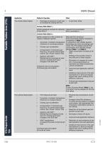
Variable Turbine Area (VTA) Two-stroke diesel engine Scavenge-air pressure at part load ▪ is increased by closing the VTA: In part load, either Economy Mode (Mode 1.) Ignition-pressure increase for reduction reduced fuel consumption of the SFOC 3) (NOx increased) or Emission Mode (Mode 2.) Ignition pressure is held constant by means of delayed injection Reduced NOx emissions (Fuel consumption lightly increased in comparison to Mode 1.). ▪ Correction of ambient-temperature In conjunction with variable injection influences on scavenge pressure technology and when accordingly optimized, the...
Open the catalog to page 6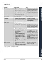
VTA opens at part load Correction of ambient-temperature influences on charge pressure Reduced fuel consumption due to increased charging efficiency when compared with blow-off valves or throttle Closing on load application to pre- ▪ vent mixture from being over-rich Elimination of blow-off valves/throttle Variation of the charge pressure to adapt to changing gas qualities Dual-fuel engine Test engine Adaptation of the charging air pres- ▪ sure to changed engine parameters VTA only on power turbine „Closing“ of the VTA for throttling of ▪ the power-turbine output Increase of the charging...
Open the catalog to page 7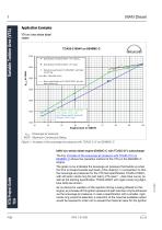
MAN Diesel Application Examples VTA on a two-stroke diesel engine TCA55-21004V on 6S46MC-C 4000 S pec ific ation TC A55-21004V, VTA c los ing S pec ific ation TC A55-21004V, VTA open 3500 Variable Turbine Area (VTA) S tandard s pec ific ation TC A55-20027 w ith fixed noz z le ring Max. allow able ps c av 3000 S am e s pec ific ation as TC A55-21004V but w ith fixed noz z le ring 2500 A ux. B lo we r switch p o int with V TA clo se d =2 7 % L o a d A ux. B lo we r switch p o int with o ld sp e c =3 2 % L o a d pscav Scavenge air pressure MCR Maximum Continuous Rating Figure 1: Increase of...
Open the catalog to page 8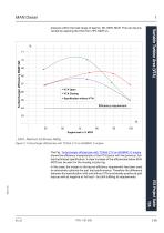
Variable Turbine Area (VTA) pressure within the load range of approx. 80-100% MCR. This can be prevented by opening the VTA from 75% MCR on. 67 VTA Open 66 VTA Closing Specification without VTA Efficiency requirement MCR Maximum Continuous Rating Figure 2: Turbocharger efficiencies with TCA55-21V on 6S46MC-C engine The Fig. Turbocharger efficiencies with TCA55-21V on 6S46MC-C engine shows the efficiency characteristic of the VTA layout with the previous, fullload optimized specification. A clear increase of the efficiencies below 85% MCR can be seen for the closing nozzle ring. In this...
Open the catalog to page 9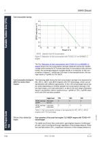
Variable Turbine Area (VTA) 1 Fuel Consumption Savings SFOC Specific Fuel Oil Consumption Figure 3: Reduction of fuel consumption with TCA55-21V on 6S46MC-C engine The Fig. Reduction of fuel consumption with TCA55-21V on 6S46MC-C engine shows the fuel consumption savings measured during the maiden voyage while closing the VTA toward part load. In accordance with previous trends, the scavenge-pressure increase results in a reduction of fuel consumption of approx. 1 g/kWh per 100 mbar; in the example shown, the savings result to 4 g/kWh at 75% MCR. Fuel Consumption Savings for The following...
Open the catalog to page 10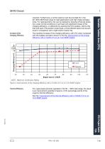
Increase of the Charging Efficiency The resulting increase of the charging efficiency with VTA when compared with the bypass concept is shown in the Fig. Improvement of the charge efficiency with a TCA55-41V on an 7L51/60DF engine. Variable Turbine Area (VTA) required. Furthermore, a control reserve must be provided for in the 50-100% MCR load range for load applications and high intake temperatures. For rigid geometry, this can be realized by blowing-off during operation under normal conditions or part load with significant losses of the charging efficiency, or efficiently by opening the...
Open the catalog to page 11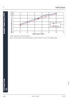
∆η=1% Engine thermal efficiency in % Variable Turbine Area (VTA) MCR Maximum Continuous Rating Figure 5: Improvement of the thermal efficiency with a TCA55-41V on an 7L51/60DF engine
Open the catalog to page 12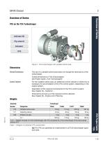
Overview of Series VTA on the TCA Turbocharger Activate 3D Fly-around Actuator VTA Figure 1: TCA turbocharger with variable turbine area Dimensions Overall Dimensions The use of a variable turbine area does not change the dimensions of the turbocharger. Overall dimensions of TCA turbochargers: see Project Guide „TCA Turbochargers“. Control Cabinet For the variable turbine area, an additional control cabinet or switch box is necessary for accomodation of the VTA control system, depending on the engine system. Description of the required components for the VTA control system: See chapter [4]...
Open the catalog to page 13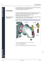
For weight information on VTA components of non-listed TCA turbochargers, please contact our technical sales department. E-mail: turbochargers@mandiesel.com Casing Positions By using the variable turbine area, there are no restrictions in terms of the turnability of individual turbocharger casings of TCA turbochargers. Tip! Possible casing positions for TCA turbochargers: see Project Guide „TCA Turbochargers“. Mounting Position of the Adjusting Device The adjusting device for the turbine nozzle ring is firmly mounted to the gasadmission casing and cannot be turned separately. The...
Open the catalog to page 14All MAN Energy Solutions - Marine catalogs and brochures
-
 CP pro peller
16 Pages
-
 Marine Engine Programme 2021
260 Pages
-
 Technology for Ecology
16 Pages
-
 EEDI
EEDI12 Pages
-
 Alphatronic 3000
42 Pages
-
 TCR TURBOCHARGER
9 Pages
-
 TCA The benchmark
9 Pages
-
 Marine engine programme
260 Pages
-
 LNG Shipping
15 Pages
-
 MAN Dual-Fuel GenSets
19 Pages
-
 ME Engines
8 Pages
-
 Hybrid Propulsion
9 Pages
-
 Four-Stroke Marine Engines
35 Pages
-
 EPROX
EPROX2 Pages
-
 Cruise & Ferry
17 Pages
-
 PRO PELLER aft ship solutions
48 Pages
-
 PACKAGE BENEFITS MAN 175D
2 Pages
-
 MAN Cryo
12 Pages
-
 Offshore Power Module
2 Pages
-
 Ready for Tier III
6 Pages
-
 MAN L51/60DF
2 Pages
-
 MAN Alpha CP Propellers Mk 3
30 Pages
-
 Man Alpha FP Propellers
16 Pages
-
 Common Rail Technical Paper
20 Pages
-
 L27/38
16 Pages
-
 L28/32DF GenSet
5 Pages
-
 L16/24
16 Pages
-
 PrimeServLube Bio P 1000
4 Pages
-
 MAN Alpha FPP Retrofit Flyer
2 Pages
-
 CP Propeller Mk.3
30 Pages
-
 Man Alpha FPP
2 Pages
-
 Alphatronic 2000 PCS
32 Pages
-
 Alphatronic 3000 PCS
2 Pages
-
 Common Rail Brochure
12 Pages
-
 OBC Vessels
4 Pages
-
 AHTS Propulsion
4 Pages
-
 48/60
48/607 Pages
-
 MAN Alpha Naval Propellers
16 Pages
-
 TCR The Cutting Edge
16 Pages
-
 MAN-Alpha FPP Brochure
16 Pages
-
 TCS-PTG TURBOCHARGER
12 Pages
-
 Marine engine 2009
232 Pages


