Catalog excerpts

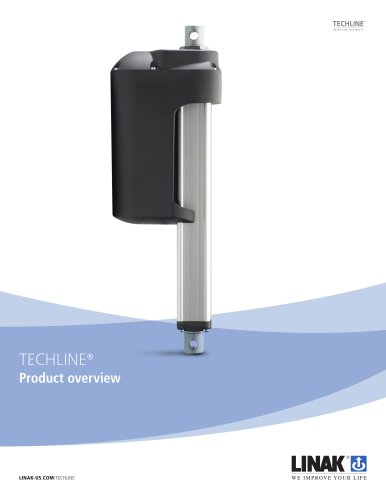
ACTUATOR LA14 Features: • 12 or 24 V DC permanent magnetic motor • Max. thrust 750 N • Max. speed up to 45 mm/sec. depending on load and spindle pitch • Stroke length from 19 to 130 mm • Compact design, built-in dimensions 245 mm (up to 345 mm) • Protection class: IP66 (dynamic) and IP69K (static) • Built-in endstop switches • Stainless steel inner tube and steel piston rod eyes Options in general: • Exchangeable cables in different lengths up to 5 m • Stainless steel piston rod eye • Special anodised housing for extreme environments • Hall effect sensor • Potentiometer - max. stroke length 100 mm • IC options including: - IC - Integrated Controller - Integrated Parallel Controller - LINbus communication - Analogue or digital feedback for precise positioning - Endstop signals - PC configuration tool Usage: • Duty cycle max. 20% (4 min. drive and 16 min. rest for 2 mm spindle pitch) and max. 40% (8 min. drive and 12 min. rest for 4 mm spindle pitch) at +5 to +40°C ambient temperature The actuator LA14 is a very tough actuator with a high IP degree and aluminium housing, making it ideal for use in harsh and demanding environments. The LA14 offers top quality in every detail and ensures reliable performance in temperatures ranging from -40° to +85 °C. With its small size the LA14 is well suited for applications that require short linear movements. This TECHLINE® actuator comes with IC - Integrated controller. For more information on our IC options, please see: www.linak.com/techline
Open the catalog to page 1
Actuator with:
Open the catalog to page 2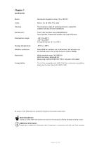
Permanent magnetic motor 12 or 24V DC The housing is made of casted aluminium, coated for outdoor use and in harsh conditions Spindle part: Inner tube: Stainless steel AISI304/SS2333 Acme spindle: Trapezoidal spindle with high efficiency Temperature range: Storage temperature: Weather protection: Rated IP66 for outdoor use. Furthermore, the actuator can be washed down with a high-pressure cleaner (IP69K) Noise level: With standard motor: 50-53dB (A) With fast motor: 58-63 dB (A) Measuring method DS/EN ISO 3743-1 actuator not loaded The LA14 is compatible with SMPS-T160 (For combination...
Open the catalog to page 3
Technical specifications Type Spindle Thrust Self-lock Self-lock Pitch max. max. max. (mm) Push/Pull (Push) (Pull) (N) (N) (N) *Typical speed 0/full load (mm/s) Stroke length *Typical Amp. at full load (A) 24V - 12V * The typical values can have a variation of ± 20% on the current values and ± 10% on the speed values. Measurements are made with an actuator in connection with a stable power supply and an ambient temperature at 20°C. Self locking ability To ensure maximum self-locking ability, please be sure that the motor is shorted when stopped. Actuators with integrated controller have...
Open the catalog to page 4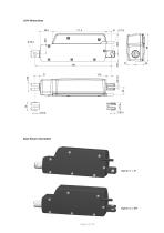
Back fixture orientation
Open the catalog to page 5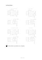
Ijgi The Piston Rod Eye is only allowed to turn 0 - 90 degrees.
Open the catalog to page 6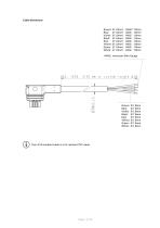
Cable dimensions Brown: Ø 1.0mm2 Blue: Ø 1.0mm2 Violet: Ø 1.0mm2 Black: Ø 1.0mm2 Red: Ø 1.0mm2 Yellow: Ø 1.0mm2 Green: Ø 1.0mm2 White: Ø 1.0mm2 *AWG: American Wire Gauge Brown: Ø 1.8mm Blue: Ø 1.8mm Violet: Ø 1.8mm Black: Ø 1.8mm Red: Ø 1.8mm Yellow: Ø 1.8mm Green: Ø 1.8mm White: Ø 1.8mm The LA14 standard cable is a UV resistant PVC cable.
Open the catalog to page 7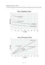
Speed and current curves - 12V motor The values below are typical values and made with a stable power supply and an ambient temperature of 20°C.
Open the catalog to page 8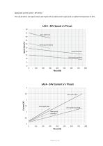
Speed and current curves - 24V motor The values below are typical values and made with a stable power supply and an ambient temperature of 20°C.
Open the catalog to page 9
Chapter 2 I/O specifications: Actuator without feedback Input/Output Permanent magnetic DC motor. To extend actuator: Connect Brown to positive To retract actuator: Connect Brown to negative Under normal conditions: 12V, max. 5A depending on load 24V, max. 2.5A depending on load To extend actuator: Connect Blue to negative To retract actuator: Connect Blue to positive
Open the catalog to page 10
I/O specifications: Actuator with endstop signals and relative positioning - Single Hall Input/Output The actuator can be equipped with Single Hall that gives a relative positioning feedback signal when the actuator moves. To extend actuator: Connect Brown to positive To retract actuator: Connect Brown to negative Under normal conditions: 12V, max. 5A depending on load 24V, max. 2.5A depending on load Signal power supply GND (-) To retract actuator: Connect Blue to positive Signal power supply (+) 12-24VDC To extend actuator: Connect Blue to negative Current consumption: Max. 40mA, also...
Open the catalog to page 11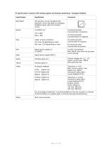
I/O specifications: Actuator with endstop signals and absolute positioning - Analogue feedback Input/Output The actuator can be equipped with electronic circuit that gives an analogue feedback signal when the actuator moves. To extend actuator: Connect Brown to positive To retract actuator: Connect Brown to negative Under normal conditions: 12V, max. 5A depending on load 24V, max. 2.5A depending on load To extend actuator: Connect Blue to negative Signal power supply (+) 12-24VDC Signal power supply GND (-) Current consumption: Max. 60mA, also when the actuator is not running Analogue...
Open the catalog to page 12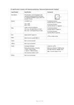
I/O specifications: Actuator with absolute positioning - Mechanical potentiometer feedback Input/Output The actuator can be equipped with mechanical potentiometer that gives an analogue feedback signal when the actuator moves. To extend actuator: Connect Brown to positive To retract actuator: Connect Brown to negative Under normal conditions: 12V, max. 5A depending on load 24V, max. 2.5A depending on load To extend actuator: Connect Blue to negative To retract actuator: Connect Blue to positive Signal power supply (+) Signal power supply GND (-) Analogue feedback Slide potentiometer, 10...
Open the catalog to page 13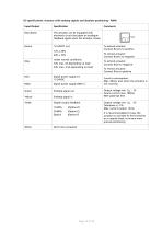
I/O specifications: Actuator with endstop signals and absolute positioning - PWM Input/Output The actuator can be equipped with electronic circuit that gives an analogue feedback signal when the actuator moves. To extend actuator: Connect Brown to positive To retract actuator: Connect Brown to negative Under normal conditions: 12V, max. 5A depending on load 24V, max. 2.5A depending on load Signal power supply (+) 12-24VDC Signal power supply GND (-) Digital output feedback 10-90% 20-80% Special To extend actuator: Connect Blue to negative To retract actuator: Connect Blue to positive...
Open the catalog to page 14All Linak catalogs and brochures
-
Control Box CO71
13 Pages
-
Foot Switch FS3
8 Pages
-
Actuator LA40
16 Pages
-
DESKLINE®
12 Pages
-
Quality Matters
8 Pages
-
Built-in DB5
4 Pages
-
Built-in DB6
8 Pages
-
Built-in actuator DB14
4 Pages
-
External charger CHJ2
4 Pages
-
Better Solutions - Better Care
28 Pages
-
Bluetooth® Adapter
4 Pages
-
Battery pack BAJ
6 Pages
-
Li-Ion battery disclaimer
2 Pages
-
Focus on Marine
24 Pages
-
TECHLINE Overview
20 Pages
-
LA36
40 Pages
-
LA31
8 Pages
-
LA25
40 Pages
-
LA23
8 Pages
-
LA12
17 Pages
Archived catalogs
-
ACTUATOR LA28 COMPACT
8 Pages
-
ACTUATOR LA28
8 Pages
-
ACTUATOR LA22
4 Pages
-
Lifting Column DL4
4 Pages
-
Dual Actuator TD1 280 SMPS
4 Pages
-
Lifting Column BL1
4 Pages
-
linear actuator la35 MODBUS
2 Pages
-
linear actuator LA35
8 Pages
-
Linear Actuator LA29
4 Pages
-
Linear Actuator LA23
4 Pages
-
Linear Actuator LA12
8 Pages


