
Catalog excerpts

Technical Datasheet The cost efficient flow indicator • Simple installation • Accurate and stable measurements • KROHNE quality
Open the catalog to page 1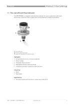
1.1 The cost efficient flow indicator The OPTIPROBE is a magnetic inductive flow indicator for use in conjunction with clean, electrically conductive fluids in pipes with nominal diameters of 80 mm and above. 1 Connection box 2 Process connection flange 3 Head with integrated coils and electrodes All wetted parts of non-corrosive materials Easy to install Pulsed DC field excitation Wide (bidirectional) measuring range Installation possible in pipelines under pressure Industries • Water • Wastewater Applications • For clean liquids with a minimum conductivity of 20 S/cm
Open the catalog to page 3
1.2 Measuring principle The OPTIPROBE is inserted through a hole drilled in the pipe. A magnetic coil located in the probe's measuring head generates a pulsed DC field perpendicular to the measuring head. This together with the movement of the fluid induces a voltage proportional to the mean flow velocity. The voltage is picked up by two electrodes fitted to the front of the probe and forwarded to a signal converter, where it is converted into a measured flow speed.
Open the catalog to page 4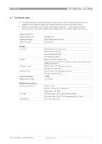
2.1 Technical data • The following data is provided for general applications. If you require data that is more relevant to your specific application, please contact us or your local sales office. • Additional information (certificates, special tools, software,...) and complete product documentation can be downloaded free of charge from the website (Downloadcenter). Measuring system Measuring principle Application range Electrically conductive fluids Measured value Flow velocity Design Features Wide range of measuring range Bidirectional measuring Non-corrosive materials Two models available...
Open the catalog to page 5
Operating conditions Temperature For Ex versions different temperatures are valid. Please refer to the relevant Ex documentation for details. Process temperature Ambient temperature PN16 (model A) Option: G 1½" (model B only) Connecting flange Chemical properties Physical condition Electrical conductivity Electrically conductive liquids 20 S/cm Installation conditions Installation Pipe must be fully filled for model A Electrodes must be perpendicular to the flow direction Weld the socket with connecting flange square to the longitudinal axis of the pipeline Probe insertion length minimum 25...
Open the catalog to page 6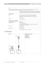
CE This device fulfils the statutory requirements of the relevent directives. The manufacturer certifies successful testing of the product by applying the conformity mark on the device. For more information on the directives, standards and the approved certifications, please refer to the declaration of conformity supplied with the device or downloadable from the manufacturer’s website. Hazardous area ATEX Please check the relevant Ex documentation for details Compact version with signal converter IFC 100 / IFC 300 II 3G; IIC T3 Other approvals and standards Protection category acc. to...
Open the catalog to page 7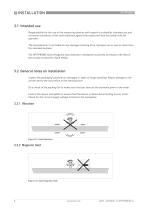
3.1 Intended use Responsibility for the use of the measuring devices with regard to suitability, intended use and corrosion resistance of the used materials against the measured fluid lies solely with the operator. The manufacturer is not liable for any damage resulting from improper use or use for other than the intended purpose. The OPTIPROBE electromagnetic flow indicator is designed exclusively to measure the flow of electrically conductive, liquid media. 3.2 General notes on installation Inspect the packaging carefully for damages or signs of rough handling. Report damage to the...
Open the catalog to page 8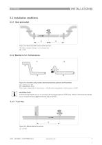
3.3 Installation conditions 3.3.1 Inlet and outlet Figure 3-3: Recommended inlet and outlet sections 1 Refer to chapter "Bends in 2 or 3 dimensions" 2 5 DN Figure 3-4: inlet when using 2 and/or 3 dimensional bends upstream of the flowmeter 1 2 dimensions = X/Y 2 3 dimensions = X/Y/Z Inlet length: using bends in 2 dimensions: ≥ 10 DN; when having bends in 3 dimensions: ≥ 20 DN INFORMATION! 2 dimensional bends occur in a vertical or horizontal plane (X/Y) only, while 3 dimensional bends occur in both vertical and horizontal plane (X/Y/Z). Figure 3-5: Distance behind T-sections 1
Open the catalog to page 9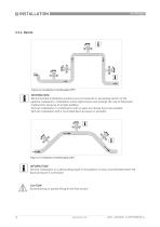
Figure 3-6: Installation in bending pipes (90°) INFORMATION! Recommended installation positions are at a lowered or ascending section of the pipeline installation. Installation at the highest point will enlarge the risk of flowmeter malfunction, because of air/gas bubbles. Vertical installation in combination with an open surcharge has to be avoided. Vertical installation with a controlled back-pressure is possible. Figure 3-7: Installation in bending pipes (45°) INFORMATION! Vertical installation on a descending slope in the pipeline is only recommended when the back-pressure is...
Open the catalog to page 10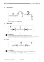
Figure 3-8: Installation in front of an open discharge Figure 3-9: Installation in front of a control valve INFORMATION! Recommended position to install a flowmeter is upstream a control valve. An electromagnetic flowmeter can be installed downstream of the control valve if there is no cavitation in the pipeline system (e.g. flow profile disturbances are resolved). Figure 3-10: Installation behind a pump INFORMATION! Recommended position to install a flowmeter is downstream a pump (on a position where the flow disturbances of the pump are resolved). An electromagnetic flowmeter can be...
Open the catalog to page 11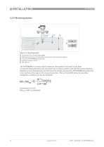
Flow profile must be fully developped Welding instructions: the electrodes must point to the side of the pipeline Insert the OPTIPROBE perpendicular Insertion length 25 mm DN 80 mm The OPTIPROBE is a sensor which measures flow speed at one point in the pipe. In case the flow speed has to be converted into a volume, please note that the measured value depends on the used diameter and the insertion length, because the OPTIPROBE decreases the inner surface of the pipe at the measuring section. The corrected GKl value for any other installation condition can be calculated as: All measures in mm...
Open the catalog to page 12All Krohne catalogs and brochures
-
OPTIMASS 2000
28 Pages
-
OPTISWITCH 4000/5000
24 Pages
-
IFC 100
36 Pages
-
OPTIFLUX 2000
48 Pages
-
OPTIMASS 7400
36 Pages
-
OPTIMASS 2400
28 Pages
-
MFC 400
36 Pages
-
OPTIMASS 1400 T
32 Pages


