
Catalog excerpts
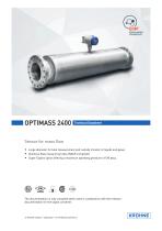
Technical Datasheet Sensor for mass flow • Large diameter for bulk measurement and custody transfer of liquids and gases • Stainless Steel measuring tubes (NACE compliant) • Super Duplex option offering a maximum operating pressure of 180 barg The documentation is only complete when used in combination with the relevant documentation for the signal converter.
Open the catalog to page 1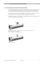
1.1 The solution for bulk mass flow measurement The OPTIMASS 2400 has been developed to meet the demanding custody transfer requirements of the oil and gas industry and is well suited to bulk measurement in many applications. The option of Super Duplex (UNS S32760) provides a maximum operating pressure of 180 barg. A high level of performance makes the OPTIMASS 2400 suitable for the bulk measurement of petroleum and oil as well as products like syrup, molasses and raw chemicals. Combined with the power of the MFC 400, the OPTIMASS 2400 will give accurate measurement of volume, mass,...
Open the catalog to page 3
Innovative design with multiple large measuring tubes, gives a high flow rate capacity Easy to drain and easy to clean Optional heating jacket High levels of accuracy for custody transfer Optimised flow divider for minimum pressure loss Super Duplex option for operating pressures up to 180 barg Secondary containment up to 150 barg Marine Oil and gas Waste water Chemical Paper and pulp Pharmaceutical Fresh water Bulk loading / unloading Custody transfer for volume and mass High volume Pipeline measurement applications Allocation metering
Open the catalog to page 4
1.2 Features and options Features • • • • • Flow rates up to 4,600,000 kg/h / 169,021 lb/min. Integrated electronics. Self draining. Best in class for zero stability. With advanced Entrained Gas Management (EGMTM) the meter maintains operation over a wide range of gas fractions and complex flow conditions. Connection options • Flange sizes from 4" / DN100 to 16" / DN400 1500 lbs / PN160. • Flanges available in Stainless Steel, Duplex and Super Duplex. Heating jacket and purge port • Heating jacket option for use with temperature dependant products. • Prevents solidification of process...
Open the catalog to page 5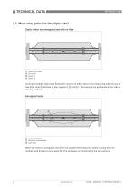
2.1 Measuring principle (multiple tube) Static meter not energised and with no flow Measuring tubes Drive coil Sensor 1 Sensor 2 A Coriolis multiple tube mass flowmeter consists of either two or four measuring tubes ① one or two drive coils ② and two or four sensors ( ③ and ④ ). The sensors are positioned either side of the drive coil / s. Energised meter 1 Measuring tubes 2 Direction of oscillation 3 Sine wave When the meter is energised, the drive coil vibrates the measuring tubes causing them to oscillate and produce a sine wave ③ . The sine wave is monitored by the two sensors.
Open the catalog to page 6
Energised meter with process flow 1 Process flow 2 Sine wave 3 Phase shift When a fluid or gas passes through the tubes, the coriolis effect causes a phase shift in the sine wave that is detected by the two sensors. This phase shift is directly proportional to the mass flow. Density measurement is made by evaluation of the frequency of vibration and temperature measurement is made using a Pt500 sensor.
Open the catalog to page 7
2.2 Technical data • The following data is provided for general applications. If you require data that is more relevant to your specific application, please contact us or your local sales office. • Additional information (certificates, special tools, software,...) and complete product documentation can be downloaded free of charge from the website (Downloadcenter). Measuring system Measuring principle Coriolis mass flow Application range Mass flow and density measurement of fluids, gases and solids Measured values Mass, density, temperature Calculated values Volume, referred density,...
Open the catalog to page 8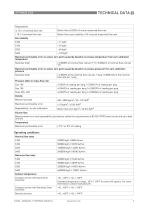
Repeatability ≥ 10:1 of nominal flow rate Better than ±0.025% of actual measured flow rate < 10:1 of nominal flow rate Better than ±zero stability x 0.5 of actual measured flow rate Maximum permissible error on sensor zero point caused by deviation in process temperature from zero calibration temperature Stainless Steel ± 0.0008% of nominal flow rate per 1°C / 0.00044% of nominal flow rate per 1°F Maximum permissible error on sensor zero point caused by deviation in process pressure from zero calibration pressure Stainless Steel ± 0.0002% of the nominal flow rate per 1 barg / 0.000014% of...
Open the catalog to page 9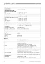
Process temperature Flanged connection Nominal pressure at 20°C / 68°F Measuring tube (Duplex UNS S31803) PED Measuring tube (Super Duplex UNS S32760) PED Outer cylinder Non PED / CRN approved Typical burst pressure > 100 barg / 1450 psig PED approved secondary containment -1...40 barg / -14.5...580 psig (S100...250 only) -1...150 barg / -14.5...2175 psig (Duplex option) Fluid properties Permissible physical condition Liquids, gases, slurries Permissible gas content (volume) Contact manufacturer for information. Permissible solid content (volume) Contact manufacturer for information....
Open the catalog to page 10
Remote versions Junction box Die cast Aluminium (polyurethane coating) Process connections Flange DIN Electrical connections Electrical connections For full details, including: power supply, power consumption etc., see technical data for the relevant converter. For full details of I/O options, including data streams and protocols, see technical data for the relevant converter. The device fulfils the statutory requirements of the relevant CE directives and UK designated standards. The manufacturer certifies that these requirements have been met by applying the CE and UKCA marks. Class I, Div...
Open the catalog to page 11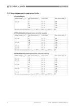
2.3 Hazardous areas temperature limits OPTIMASS 2000F Ambient temp. Tamb °C Temp. class Minimum process temperature: Tamb ≥ -35°C Tm = -50°C, Tamb <-35°C Tm = -40°C OPTIMASS 2400C with aluminium converter housing Ambient temp. Tamb °C Temp. class Minimum process temperature: Tamb ≥ -35°C Tm = -50°C, Tamb <-35°C Tm = -40°C OPTIMASS 2400C with Stainless Steel converter housing Ambient temp. Tamb °C Temp. class Minimum process temperature: Tamb ≥ -35°C Tm = -50°C, Tamb <-35°C Tm = -40°C
Open the catalog to page 12All Krohne catalogs and brochures
-
OPTIMASS 2000
28 Pages
-
OPTIPROBE
16 Pages
-
OPTISWITCH 4000/5000
24 Pages
-
IFC 100
36 Pages
-
OPTIFLUX 2000
48 Pages
-
OPTIMASS 7400
36 Pages
-
MFC 400
36 Pages
-
OPTIMASS 1400 T
32 Pages


