- Products
- Catalogs
- News & Trends
- Exhibitions
OPTIFLUX 2000
1 /48Pages

OPTIFLUX 2000
1 /48Pages
Catalog excerpts

Technical Datasheet Electromagnetic flow sensor • For all water and wastewater applications • Wide range of approvals for potable water • Robust, fully welded construction with full bore pipe The documentation is only complete when used in combination with the relevant documentation for the signal converter.
Open the catalog to page 1
1.1 Reliable solution for the water and wastewater industry The OPTIFLUX 2000 is designed to meet the demands for all water and waste water applications including groundwater, potable water, waste water, sludge and sewage, industry water and salt water. The OPTIFLUX 2000 has a field proven and unsurpassed lifetime. This is assured by the fully welded construction, full bore pipe, absence of moving parts and wear resistant liner materials. The flow sensor has the widest diameter range available in the market: from DN25 up to DN3000. 1 Robust fully welded construction 2 Diameter range: DN25...DN3000...
Open the catalog to page 3
Rugged liners suitable for any water and wastewater application Proven and unsurpassed lifetime, huge installed base Tamper proof, fully welded construction, also available in customer specific constructions Drinking water approvals including KTW, KIWA, DVGW, ACS, NSF, WRAS Suitable for subsoil installation and constant flooding (IP68) Bi-directional flow metering Compliant with requirements for custody transfer (MID MI-001, OIML R49, ISO 4064, EN 14154) Standard in house wet calibration of flow sensors up to diameter DN3000 Easy installation and commissioning No grounding rings with virtual...
Open the catalog to page 4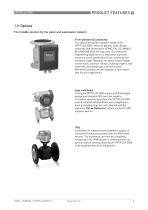
1.2 Options The reliable solution for the water and wastewater industry From standard to customized For easy ordering the standard range of the OPTIFLUX 2000 covers all popular sizes, flange materials and connections (ASME, EN, JIS, AWWA). But KROHNE does not stop here. Our extensive engineering department is dedicated to provide solutions for all specifications not covered by our standard range. Requests for special sizes, flange connections, pressure ratings, building lengths, and materials, will always get a serious review. Whenever possible we will engineer a flow meter that fits your application....
Open the catalog to page 5
Custody transfer In combination with the IFC 300 signal converter the OPTIFLUX 2000 is suitable for custody transfer applications. It meets the requirements of OIML R49 and can be verified according to Annex MI-001 of the Measuring Instruments Directive (MID) / UK Regulation 2016. All water meters for legal metrology purposes in Europe require certification under the MID. The EC type examination certificate for the OPTIFLUX 2300 is valid for the compact and the remote version and applies for forward and reverse flow.
Open the catalog to page 6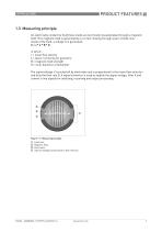
1.3 Measuring principle An electrically conductive fluid flows inside an electrically insulated pipe through a magnetic field. This magnetic field is generated by a current, flowing through a pair of field coils. Inside of the fluid, a voltage U is generated: U=v*k*B*D in which: v = mean flow velocity k = factor correcting for geometry B = magnetic field strength D = inner diameter of flowmeter The signal voltage U is picked off by electrodes and is proportional to the mean flow velocity v and thus the flow rate Q. A signal converter is used to amplify the signal voltage, filter it and convert...
Open the catalog to page 7
2.1 Technical data • The following data is provided for general applications. If you require data that is more relevant to your specific application, please contact us or your local sales office. • Additional information (certificates, special tools, software,...) and complete product documentation can be downloaded free of charge from the website (Downloadcenter). Measuring system Measuring principle Application range Electrically conductive fluids Measured value Primary measured value Flow velocity Secondary measured value Volume flow Design Features Fully welded maintenance-free flow sensor....
Open the catalog to page 8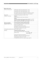
Measuring accuracy Maximum measuring error IFC 050: down to 0.5% of the measured value ± 1 mm/s IFC 100: down to 0.3% of the measured value ± 1 mm/s IFC 300: down to 0.2% of the measured value ± 1 mm/s The maximum measuring error depends on the installation conditions. For detailed information refer to Measuring accuracy on page 20. ± 0.1% of the measured value, minimum 1 mm/s Calibration / Verification Standard: 2 point calibration by a direct volume comparison. Optional: Verification to Measurement Instrument Directive (MID), Annex MI-001. Standard: Verification at Ratio (Q3/Q1) = 80, Q3 ...
Open the catalog to page 9
Operating conditions Temperature For detailed information in pressure / temperature refer to Pressure derating on page 21. For Ex versions different temperatures are valid. Please refer to the relevant Ex documentation for details. Process temperature Hard rubber liner: -5...+80°C / +23...+176°F Polypropylene liner: -5...+90°C / +23...+194°F Ambient temperature Standard (with aluminum signal converter housing): standard flanges -20…+65°C / -4…+149°F Option (with aluminum signal converter housing): low temperature carbon steel flanges or stainless steel flanges -40…+65°C / -40…+149°F Option (with...
Open the catalog to page 10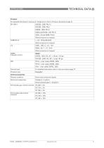
Pressure For detailed information in pressure / temperature refer to Pressure derating on page 21. EN 1092-1 1...24": 150 & 300 lb RF Other pressures on request DN50...1000 / 2...40": 10 K DN25...40 / 1...1½": 20 K Other pressures on request PN 16 - 6 bar rated; DN700...2000 PN 10 - 6 bar rated; DN700...2000 PN 6 - 2 bar rated; DN700...2000 Vacuum load For detailed information refer to Vacuum load on page 23. Pressure loss Chemical properties Physical condition Electrically conductive liquids Electrical conductivity Standard: 5 µS/cm Demineralised water: 20 µS/cm Permissible gas content (volume)...
Open the catalog to page 11
Installation conditions Installation Assure that the flow sensor is always fully filled. For detailed information refer to Installation on page 30. Flow direction Forward and reverse Arrow on flow sensor indicates flow direction. For detailed information refer to Dimensions and weights on page 24. Materials Flow sensor housing Sheet steel Other materials on request Measuring tube Austenitic stainless steel Carbon steel Other materials on request Standard: DN25...150 / 1...6": polypropylene DN200...3000 / 8...120": hard rubber Option: DN25...150 / 1...6": hard rubber Protective coating On exterior...
Open the catalog to page 12All Krohne catalogs and brochures
 OPTIPROBE
16 Pages
 IFC 100
36 Pages
 OPTIMASS 7400
36 Pages
 OPTIMASS 2000
28 Pages
 MFC 400
36 Pages
 OPTISWITCH 4000/5000
24 Pages
 OPTIMASS 2400
28 Pages
 OPTIMASS 1400 T
32 Pages
