- Products
- Catalogs
- News & Trends
- Exhibitions
IFC 100
1 /36Pages

IFC 100
1 /36Pages
Catalog excerpts

Technical Datasheet Signal converter for electromagnetic flowmeters • Extended accuracy option • Diagnostics of device and application • Certified for use in hazardous areas The documentation is only complete when used in combination with the relevant documentation for the flow sensor.
Open the catalog to page 1
1.1 The all-round solution The IFC 100 electromagnetic signal converter combines an attractive price with a wide range of features and benefits including an excellent measuring accuracy. The signal converter is compatible with almost any flow sensor in the OPTIFLUX and WATERFLUX range. The signal converter supplies the current required by two field coils to generate a magnetic field.It converts the flow proportional signal voltage into digital values and filters out electrical noise and interference signals. From the filtered signal, the flow velocity, the volume flow and the mass flow are calculated....
Open the catalog to page 3
Highlights For operation with a wide range of OPTIFLUX and WATERFLUX flow sensors For flow sensors over a diameter range from DN2.5 up to DN1200 Housing in aluminium with a polyester topcoat or in stainless steel (option) Tropicalized electronics to protect it from humidity (option) Available outputs: 4...20 mA current output, pulse/frequency output and status output/limit switch • Control input option • • • • • • HART® as standard • Power supply via 100…230 VAC (standard) or 24 VDC or 24 VAC/DC (optional) • Clearly readable values due to angle of the signal converter housing which prevents dirt...
Open the catalog to page 4
1.2 Options and variants Compact or remote wall-mounted housing For an optimal reading of the display, the compact variant comes in a 0° and a 45° version. The signal converter can be rotated in 90° increments to suit different installation positions. The compact 0° version is designed for flowmeters in vertical pipelines, the compact 45° version for horizontal installations. The wall mounted signal converter can be installed remotely for locations where the flow sensor is difficult to access, or ambient temperature conditions or vibrations prevent a compact variant. (signal converter in wall-mounted...
Open the catalog to page 5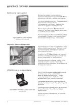
Stainless steel housing (option) Whereas the standard housing material is aluminium with a polyester topcoat, the IFC 100 can optionally be ordered in a stainless steel housing. The robust housing is suitable for many applications in the food and beverage industry. It is designed for environments where extreme chemicals or aggressive cleaning are used. The housing is dual rated to IP67/69 protection category to resist wash down cleaning and no glass is used for the display window. The mounting angle for the compact housing and the rounded edges in the wall-mount position prevent dirt and water...
Open the catalog to page 6
1.3 Signal converter/flow sensor combination possibilities Flow sensor Flow sensor + signal converter IFC 100 Compact (0°/45° version) Remote wall-mounted housing 1.4 Measuring principle An electrically conductive fluid flows inside an electrically insulated pipe through a magnetic field. This magnetic field is generated by a current, flowing through a pair of field coils. Inside of the fluid, a voltage U is generated: U=v*k*B*D in which: v = mean flow velocity k = factor correcting for geometry B = magnetic field strength D = inner diameter of flowmeter The signal voltage U is picked off by...
Open the catalog to page 7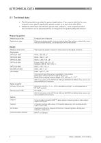
2.1 Technical data • The following data is provided for general applications. If you require data that is more relevant to your specific application, please contact us or your local sales office. • Additional information (certificates, special tools, software,...) and complete product documentation can be downloaded free of charge from the website (Downloadcenter). Measuring system Measuring principle Application range Continuous measurement of current volume flow, flow velocity, conductivity, mass flow (at constant density), coil temperature of the flow sensor Design Modular construction The...
Open the catalog to page 8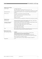
Display and user interface Graphic display LC display, backlit white. Size: 128 x 64 pixels, corresponds to 59 x 31 mm = 2.32" x 1.22" Ambient temperatures below -25°C / -13°F may affect the readability of the display. Operating elements 4 push buttons for operator control of the signal converter without opening the housing. Remote control PACTwareTM (including Device Type Manager (DTM)) HART® Hand Held Communicator from Emerson Process AMS® from Emerson Process PDM® from Siemens All DTMs and drivers are available free of charge from the manufacturer's website. Display functions Operating menu...
Open the catalog to page 9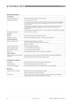
Operating conditions Temperature Process temperature Refer to the technical data of the flow sensor. Ambient temperature -40…+65°C / -40…+149°F For compact devices is the maximum ambient temperature reduced depending on the flow sensor type and the process temperature. For details refer to the flow sensor manual. It is advised to protect the signal converter from external heat sources such as direct sunlight as higher temperatures reduce the life cycle of electronic components. Ambient temperatures below -25°C / -13°F may affect the readability of the display. Storage temperature Pressure Medium...
Open the catalog to page 10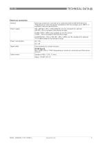
Electrical connection General Electrical connection is carried out in conformity with the VDE 0100 directive "Regulations for electrical power installations with line voltages up to 1000 V" or equivalent national specifications. Power supply 100…230 VAC (-15% / +10%), 50/60 Hz; non-Ex: standard; Ex: optional 240 VAC + 5% is included in the tolerance range. 24 VDC (-55% / +30%); only available as non-Ex version 12 VDC - 10% is included in the tolerance range. 24 VAC/DC (AC: -15% / +10%; DC: -25% / +30%); non-Ex: standard; Ex: optional 12 V is not included in the tolerance range. Power consumption...
Open the catalog to page 11
Inputs and outputs General All outputs are electrically isolated from each other and from all other circuits. All operating data and output values can be adjusted. Vext = external voltage; RL = load + resistance; V0 = terminal voltage; Inom = nominal current Current output Output data Volume flow, mass flow, diagnostic value, flow velocity, coil temperature, conductivity Without HART® Q = 0%: 0…20 mA; Q = 100%: 10…21.5 mA Error identification: 20…22 mA With HART® Q = 0%: 4…20 mA; Q = 100%: 10…21.5 mA Error identification: 3…22 mA Operating data Active Vint, nom = 20 VDC I 22 mA RL 750 HART®...
Open the catalog to page 12All Krohne catalogs and brochures
 OPTIPROBE
16 Pages
 OPTIFLUX 2000
48 Pages
 OPTIMASS 7400
36 Pages
 OPTIMASS 2000
28 Pages
 MFC 400
36 Pages
 OPTISWITCH 4000/5000
24 Pages
 OPTIMASS 2400
28 Pages
 OPTIMASS 1400 T
32 Pages
