
Catalog excerpts
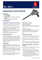
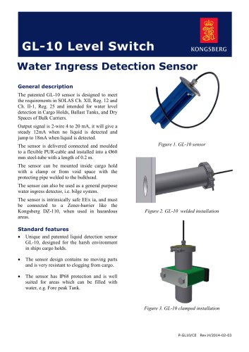
GL-3D/.. Capacitive Level Switch Features • • • • No moving parts Easy installation Wetted parts in AISI 316 and PTFE (Teflon) Built in temperature sensor (Pt100) Description Application and general description Measuring principle The GL-3D is a high quality level switch with capacitive element, and built in temperature sensor. Capacitive measurement The tip is made of Teflon, see Fig. 3. In the Teflon tip there is an electrode, where the capacitance is measured. The switch can be used as a sensing device in most liquids with low or medium conductivity. This will include all oil products and most chemicals. Limitations: The level switch is not recommended for good conducting liquids making deposits on the tip of the sensor. NOTE! Not to be used in polluted seawater! Temperature measurement Temperature measurements is done by using a Pt100 element, located close to the tip of the sensors, see Fig. 3. Connection to the monitoring system is 3wire. Mechanical design Electrical connection The mechanical design is shown in Fig. 3. The level switch can be delivered in two mechanical versions, see Fig. 5 and 6. Connection box in Al-alloy with protection grade IP56 to be used in engine room or equivalent, see Fig. 5. Connection box in AISI 316 and protection grade IP67 to be used in more rough conditions, see Fig. 6. A Cu-screened cable, with intact screen, must always be used between the switch and monitoring system. Installation Important! Minimum 15 mm free space in all directions from Teflon tip to tank wall or other obstacles! The level switch can be installed both vertically and horizontally. Fig. 4 shows an application for starting a pump at minimum level and stopping the pump at maximum level. The level switch is installed horizontally from the side of the tank. Fasten coupling must be ordered separately. As a standard we recommend: FS12-B12 with ISO228G1/2 or FS12-B34 with ISO228-G3/4. Minimum cross section of the cable is 0.5 mm2. The Cu-screen must be grounded in the cable gland, see Fig. 1. On the monitoring side, the screen must be grounded as near the inlet to the monitoring cabinet as possible. Test after installation, “short pins for test” The level switch is delivered in two functional versions, the GL-3D/N and the GL-3D/R. Description of the normal version, the GL-3D/N: 1) With dry sensor tip, the relay will be disconnected and the light emitting diode (LED) will be dark. No reaction by shorting the test pins. 2) When a liquid reaches the tip, the relay will be operated and the LED will be illuminated. 3) With the sensor tip wet, perform functional test by shorting the test pins (Fig. 2). P-GL3D/CE rev. A
Open the catalog to page 1
When “shorting test pins” are performed, dry condition is simulated and the level switch will Type GL-3D/N Condition sensor tip Dry Wet Wet, test pins shorted, dry condition simulated Dry Wet Dry, test pins shorted, wet condition simulated respond, see table below. The GL-3D/R will have the opposite function, see table below. Light emitting diode (LED) Dark Illuminated Dark Illuminated Dark Dark Relay Disconnected (not operated) Operated Disconnected Operated Disconnected Disconnected Drawings Drawings Fig. 2 Electrical connection Power, relay, Pt100
Open the catalog to page 2
Fig. 5 The level switch GL-3D/x-0-x Dimensional sketch (IP56) Fig. 6 The level switch GL-3D/x-1-x Dimensional sketch (IP67) Ordering key The insertion length and type of connection head must be specified: GL-3D/ – – N = Relay operated when wet sensor R = Relay operated when dry sensor Insertion length in mm: 100 – 150 – 200 – 250 Mechanical design: 0: See Fig. 5 IP56 1
Open the catalog to page 3
Technical specifications Power supply: Normal current consumption: Maximum current consumption: Relay alarm output: 24 VDC nominal (19 to 32 VDC) Approximately 25 mA Approximately 40 mA 2 potential free contacts 120 V/0.5 A or 32 VDC/0.5 A NOTE! Not to be used in polluted water! Installation Switching accuracy oil Switching accuracy water Accuracy, vertical installation 8 mm up on tip ±2 mm 0.5 mm up on tip ±0.2 mm Operating ambient temperature: Storage temperature: Sensor tip continuous temperature: Sensor tip short time: Minimum distance from Teflon tip: Material sensor tip, wetted part:...
Open the catalog to page 4All Kongsberg Maritime catalogs and brochures
-
 GL-10
GL-102 Pages
-
 K-Bridge AP
2 Pages
-
 K-THRUST
2 Pages
-
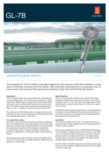 GL-7B
GL-7B2 Pages
-
 K-BRIDGE MULTI-INDICATOR
2 Pages
-
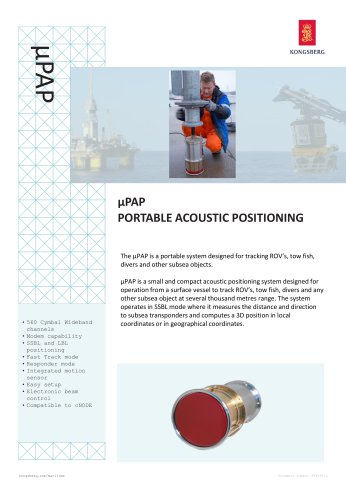 μPAP
μPAP3 Pages
-
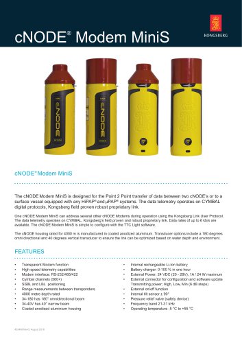 cNODE® Modem MiniS
2 Pages
-
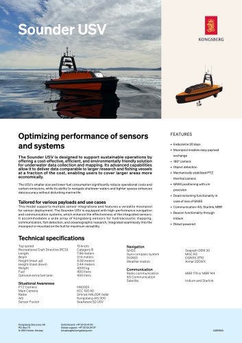 Sounder
1 Pages
-
 AutoChief 600
2 Pages
-
 Hugin product specification
2 Pages
-
 DP Operator Station-650
2 Pages
-
 Compact DP Operator Station
2 Pages
-
 Dynamic positioning systems
9 Pages
-
 DP Logger
2 Pages
-
 K-Thrust TC
4 Pages
-
 K-Thrust RCS
2 Pages
-
 cC-1
cC-12 Pages
-
 cJoy WT
2 Pages
-
 cJoy OT
2 Pages
-
 cJoy Controller
2 Pages
-
 cJoy PE
2 Pages

Archived catalogs
-
 EM 2040C MKII
2 Pages
-
 DRS 500/IMS 500
2 Pages
-
 The Seapath family
12 Pages
-
 mini MRU
2 Pages
-
 Vessel motion monitoring
2 Pages
-
 Company brochure
19 Pages
-
 The MRU Family of Products
16 Pages
-
 company borchure 2019
13 Pages
-
 MGC R2
2 Pages
-
 DP alert system
2 Pages
-
 Automatic DP alert
2 Pages
-
 EELUME500
2 Pages
-
 REMUS 6000
2 Pages
-
 REMUS 600
2 Pages
-
 Naval AUV product range
16 Pages
-
 Munin AUV
2 Pages
-
 SEAGLIDER
2 Pages
-
 SEAGLIDER C2
2 Pages
-
 SEAGLIDER M6
2 Pages
-
 HISAS 1030
12 Pages
-
 Vessel performance optimizer
20 Pages
-
 K-Chief Marine automation system
16 Pages
-
 Dynamic Positioning Logger
2 Pages
-
 KM-workboats-folder
4 Pages
-
 KM OSV brochure
8 Pages
-
 HiPAP Family brochure
24 Pages
-
 K-Nav navigation products
8 Pages
-
 REMUS catalog
8 Pages
-
 OE14-408
2 Pages
-
 OE14-110/111
2 Pages
-
 oe15-108/109
2 Pages
-
 OE15-110/111
2 Pages
-
 Hugin family of AUV's
28 Pages
-
 Motion Gyro Compass
2 Pages
-
 Kongsberg GlobalSim
5 Pages
-
 K-CHIEF 700
9 Pages
-
 K-CHIEF 600
4 Pages
-
 OE14-372/373
1 Pages
-
 OE14-364/365
1 Pages
-
 OE14-308
1 Pages
-
 OE14-208
1 Pages
-
 oe15-358/359
1 Pages
-
 OE15-100c/101c
1 Pages
-
 OE13-124/125
2 Pages
-
 OE14-522
1 Pages
-
 oe14-502
1 Pages
-
 AIS 200
2 Pages
-
 HPR 418
2 Pages
-
 HPR 408S
2 Pages
-
 RADius
2 Pages
-
 DPC-3
DPC-32 Pages
-
 DPC-1
DPC-12 Pages
-
 OS-650-DP
2 Pages
-
 DARPS 116
2 Pages
-
 Offshore Support Vessels
8 Pages
-
 Know exactly where you stand
4 Pages
-
 Offshore support vessels
8 Pages
-
 REMUS 100
6 Pages
-
 The hydrographic product family
32 Pages
-
 AIS 200 BF
2 Pages
-
 GeoSwath Plus
16 Pages
-
 Engine Room Simulator
16 Pages
-
 Pressure sensors
5 Pages
-
 Signal converters
5 Pages
-
 Products for workboats
4 Pages
-
 Products for tankers
32 Pages
-
 LNG vessel automation
12 Pages
-
 Cruise
20 Pages
-
 Yacht brochure
12 Pages
-
 K-MASTER WORKSTATION
12 Pages
-
 cJoy system
2 Pages
-
 AIS 200 P
2 Pages


