
- Catalogs
- Instromet Weather Systems Ltd
- Instromet Wind / Temperature Sensor wiring diagram

Instromet Wind / Temperature Sensor wiring diagram

Instromet Wind / Temperature Sensor wiring diagram
The Instromet Wind/Temperature Sensor requires a six-core cable connection via a terminal block on the sensor bracket. The wiring color codes are as follows: Red for +5V supply, Yellow for Wind Direction input, Black for Ground, Blue for Wind Speed input, Green and White for Temperature input.
The sensor should be mounted on a mast 25-50mm in diameter, positioned away from obstructions like chimneys and trees to avoid wind turbulence. It should be at least 2 meters above roof peaks and aligned to the North using a compass. The cable should be secured and not placed near power or transmitter cables. The junction box cover should not be sealed as it needs to breathe.
If the sensor is not functioning, ensure the power supply is on and correctly wired. For incorrect wind direction readings, verify the sensor's North alignment and wiring. If wind speed is not registering, check the anemometer cups and wiring, especially the blue wire. Voltage checks can be performed: Supply voltage (Black-Red) should be 5V DC, Wind Speed (Black-Blue) should be 2.5V AC with cups rotating, and Wind Direction varies from 0V to 4.5V DC depending on direction.
For further assistance, contact Instromet Weather Systems Ltd at 01692 502800 or return the sensor for checking or replacement.
Catalog excerpts
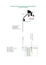
Instromet Wind / Temperature Sensor wiring diagram Yellow = Wind Direction input Blue = Wind Speed input Green = Temp input White = Temp input
Open the catalog to page 1
Installation Instruction Sensor wiring The six core cable should be connected to the individual sensor via the terminal block on the sensor bracket. This can be accessed by removing the black cover, where a wiring colour identification label will be found. Roof Top Wind/Temperature Sensor This unit should be mounted on a mast of 25-50mm (1-2inches) in diameter, as high and as far away as possible from chimneys, roof peaks, buildings, trees and transmitter aerials which may cause wind turbulence or interference. Where possible the roof top wind sensor should be mounted at least 2 metres above...
Open the catalog to page 2All Instromet Weather Systems Ltd catalogs and brochures
 Kestrel 4500 measures
2 Pages
 Kestrel 3000 measures
2 Pages
 Kestrel 2000 measures
2 Pages
 Kestrel 1000 measures
2 Pages
 instromet
16 Pages
 Humidity
2 Pages


