

881A

881A
Catalog excerpts

IMAGENEX MODEL 881A DIGITAL MULTI-FREQUENCY IMAGING SONAR ROV, AUV, & UUV Offshore Oil & Gas Sunken Timber Recovery Diving Support Surveying Search & Recovery Inspection Underwater Archaeology Scientific Research Programmable Multi-frequency High performance Lower cost Low power Simple set-up and installation Digital telemetry Full scale range from 1 m to 200 m Compact size Communication format available to user Now with Multi-frequency Sonar, operators can generate highly detailed full-scale images with just one unit. The 881A is a programmable multi-frequency digital imaging sonar that you can operate using default frequency settings or customize the configurations for your own situation. High performance, lower cost, low power and simple set-up and installation, make this sonar perfect for the largest ROV’s to the smallest inspection ROV’s, plus AUV or UUV applications. Specifications subject to change without notice Copyright © 2002 - 2013 Imagenex Technology Corp.
Open the catalog to page 1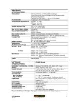
HARDWARE SPECIFICATIONS: FREQUENCY TRANSDUCER TRANSDUCER BEAM WIDTH RANGE RESOLUTION MIN. DETECTABLE RANGE MAX. OPERATING DEPTH MAX. CABLE LENGTH INTERFACE CONNECTOR POWER SUPPLY DIMENSIONS (for both depth ratings) WEIGHT: In Air 310 kHz, 675 kHz, or 1 MHz (default settings) -Other frequencies can be selected through programmable software configurations (Tunable from 280 kHz to 1.1 MHz in 5 kHz steps) Imaging type, fluid compensated 310 kHz: 4° x 40° 675 kHz: 1.8° x 20° 1 MHz: 0.9° x 10° 1 m – 4 m: 2 mm (0.08”) 5 m & up: 10 mm (0.4”) 150 mm (6”) 1000 m and 3000 m available 1000 m on typical twisted...
Open the catalog to page 2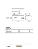
ORDERING INFORMATION: 1000 m UNIT 3000 m UNIT RS-232 End mount connector Right angle connector Interface source code in “C” (TEST881A.C) Standard Standard Option Option Option Option Product and company names listed are trademarks or trade names of their respective companies.
Open the catalog to page 3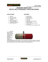
IMAGENEX MODEL 881A DIGITAL MULTI-FREQUENCY PROFILING SONAR Profiling ROV, AUV & UUV Offshore Oil & Gas Surveying Dam Face Inspection Pipeline Inspection Underwater Archaeology Scientific Research Programmable Multi-frequency High performance Lower cost Low power Simple set-up and installation Digital telemetry 1 to 100 m operation (full scale) Compact size Communication format available to user Now with Multi-frequency Sonar, operators can fine-tune their profiling range resolution. The Model 881A Profiling Sonar Head is a programmable multi-frequency digital scanning sonar that you can operate...
Open the catalog to page 4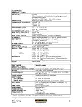
HARDWARE SPECIFICATIONS: FREQUENCY TRANSDUCER TRANSDUCER BEAM WIDTH RANGE RESOLUTION MIN. DETECTABLE RANGE MAX. OPERATING DEPTH MAX. CABLE LENGTH INTERFACE CONNECTOR POWER SUPPLY DIMENSIONS (for both depth ratings) WEIGHT: In Air 675 kHz -Other frequencies can be selected through programmable software configurations (Tunable from 600 kHz to 1 MHz in 5 kHz steps) Profiling type, fluid compensated 600 kHz: 2.4° 675 kHz: 2.1° 1 MHz: 1.4° 1 m – 4 m: 2 mm (0.08”) 5 m & up: 10 mm (0.4”) 150 mm (6”) 1000 m and 3000m available 1000 m on typical twisted shielded pair (RS-485) RS-485 serial interface @...
Open the catalog to page 5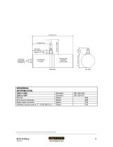
ORDERING INFORMATION: 1000 m UNIT 3000 m UNIT RS-232 End mount connector Right angle connector Interface source code in “C” (TEST881A.C) Standard Standard Option Option Option Option Product and company names listed are trademarks or trade names of their respective companies.
Open the catalog to page 6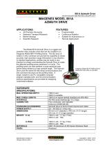
881A Azimuth Drive 445-019 AUGUST 2002-REVISED JANUARY 2011 IMAGENEX MODEL 881A AZIMUTH DRIVE APPLICATIONS: • • • • 3D Precision Surveying Sediment Transport Research Marine Geology Scientific Research Programmable Continuous Rotation Suitable for Autonomous or Remote Deployment The Model 881A Azimuth Drive is a rugged and powerful rotary actuator drive that can be coupled to an Imagenex Model 881A Profiling Sonar. The two axes of rotation in this combined unit provide the capability to obtain accurate, high resolution range information in any direction. In standard applications, profiles may...
Open the catalog to page 7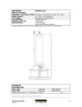
SOFTWARE SPECIFICATIONS: WINDOWS™ OPERATING SYSTEM AZIMUTH ANGLE FILE FORMAT RECOMMENDED MINIMUM COMPUTER REQUIREMENTS: Windows™ 95, 98, Me, NT*, 2000*, XP*, Vista* 0° – 359.7°, 0.3° increments (filename).81a, (filename).xyz 100 MHz Pentium 16 MB RAM 1 GB Hard Disk 800 x 600 x 256 colour graphics * Requires Win881A.exe v2.00 or higher (Free upgrade available for older versions – Contact Imagenex) ORDERING INFORMATION: 1000 m UNIT 3000 m UNIT Interface source code in “C” (TESTAZIM.C) Standard Standard Option Product and company names listed are trademarks or trade names of their respective companies....
Open the catalog to page 8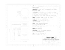
PLAN VIEW RIGHT ANGLE SIDE VIEW FREQUENCY: Tunable. Three default settings of 330kHz TRANSDUCER: Oil filled protective transducer housing. - Operater can select a frequency of his own choosing other than the default settings. — 360 degree continuous rotation. — Polar mode, sector mode, single side scan mode. RANGE: Full scale range is from 1M - 200M POWER: 24 VDC less than 5 Watts DEPTH: 1000M Aluminium housing MATERIALS: 6061T6 Aluminum, Polyurethane, 300 series stainless steel, Epoxy resin. FINISH: Hard Anodised TECHNOLOGY CORPORATION 209-1875 BROADWAY STREET, PORT COQUITLAM, B.C. CANADA, V3C...
Open the catalog to page 9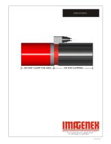
AZIMUTH DRIVE DO NOT CLAMP THIS AREA
Open the catalog to page 10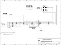
HEAD POWER SERIAL PORT TEST CABLE PINOUT IS FOR INDUSTRIAL COMPUTER SOURCE IMAGENEX Technology Corp. MODEL 881A SONAR HEAD TEST CABLE Document Number
Open the catalog to page 11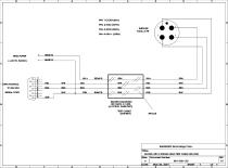
HEAD POWER SERIAL PORT TEST CABLE IMAGENEX Technology Corp. MODEL 881A SONAR HEAD TEST CABLE (RS-232) Document' Number
Open the catalog to page 12
IMAGENEX MODEL 881A SONAR 1. Remove the green nylon cord that secures the electronics housing. Don't remove the cord that secures the red polyurethane dome as it contains oil. 2. Gently wiggle the electronics housing away from the middle bulkhead section ensuring that the O-Ring remains clean and intact. 3. Locate all suitcase jumper positions on the top circuit board (PCB 130-008.V2). - install jumpers JP11, JP13 and JP 17. Remove all other jumpers. - install jumpers JP12, JP14, JP15 and JP18. Remove all other jumpers. 4. Ensure that the O-Ring and O-Ring surfaces are clean and replace the housing....
Open the catalog to page 13All Imagenex Technology Corp. catalogs and brochures
 881L
881L53 Pages
 862 Analog Altimeter
2 Pages
 852 Ultra-Miniature
3 Pages
 852 Echo Sounder Kit
3 Pages
 852 Echo Sounder
2 Pages
 837A 6000 m 120° x 20°
3 Pages
 878 ?RGB? SIDESCAN SONAR
3 Pages
 IMAGENEX DT100 SIR
3 Pages
 DT100_Specs
3 Pages
 886_BFS_Specs_rev1
3 Pages
 831A_Pipe_Profiling_Specs
2 Pages
 878_RGB_Specs_rev1
3 Pages
 965_Imaging_Specs_rev2
4 Pages
 Sidescan_Sonar_Kit
2 Pages
 872_YellowFin_Specs_rev3
2 Pages
 Sportscan_Specs
2 Pages
 881A_Imaging_Specs_rev2
3 Pages
 881L_Imaging_Specs_rev2
3 Pages
 881L_Profiling_Specs_rev1
3 Pages
 851_Specs
2 Pages
 881_Profiling_Specs
3 Pages


