- Catalogs
- Hydraulic Projects
- Sectional Spool Valve Manual
- Products
- Catalogs
- News & Trends
- Exhibitions
Sectional Spool Valve Manual
1 /36Pages

Sectional Spool Valve Manual
1 /36Pages
Catalog excerpts
Sectional Spool Valve Manual
Open the catalog to page 1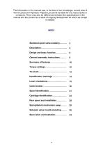
The information in this manual was, to the best of our knowledge, correct when it went to press and Hydraulic Projects Ltd cannot be liable for any inaccuracies or omissions. There may also be differences between the specifications in the manual and the product as a result of ongoing development for which we accept no liability. General assembly instructions…...…. Identification markings ..…..…..……… Lever orientations……..……..………… Code breaker……..………..….………… Spool identification……….….………… Cartridge identification………...………
Open the catalog to page 2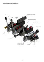
Sectional spool valve anatomy Solenoid spool section Inlet cover A Port B Port Manual spool section Ancillary valve Main relief valve Outlet cover Spool section with Ancillary interface
Open the catalog to page 3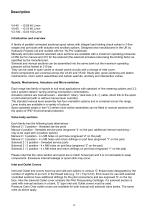
V4-40 – G3/8 40 L/min V5-60 – G1/2 60 L/min V3-100 – G3/4 100 L/min Introduction and overview A family of parallel connected sectional spool valves with integral load holding check valves in 3 flow ranges and port sizes with actuator and ancillary options. Designed and manufactured in the UK by Hydraulic Projects Ltd and marked with the ‘Hy-Pro’ trademark. Manually and pilot solenoid operated valve sections are available with a maximum operating pressures of 250 bar for manual and 210 for the solenoid (the solenoid armature tube being the limiting factor as specified by the manufacturer). Solenoid...
Open the catalog to page 4
Main Relief Valve Direct acting or pilot operated main relief valve options are available for each range and fit into the same Inlet cover cavity. All relief valves are factory set at 140 bar @ 30 L/min. unless otherwise requested. Solenoid Pilot Controlled Sections The solenoid version operates via a valve in the Outlet cover to provide pilot pressure to initially move the spool. Solenoid coils are 24w and available in 12 and 24v DC or 110v AC. Black 90º IP67 Hirschman connectors for use with Ø 4 – 9 mm cable, 1.5 mm2 max. conductor are supplied as standard. Because is a piloted system, when...
Open the catalog to page 5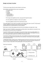
Design and basic function The three valve ranges follow the same hydraulic circuit layout. Each SPOOL VALVE SECTION has seven cast galleries 2 x through centre 2 x return 2 x service 1 x parallel - and two drillings 1 x pilot pressure line 1 x pilot return line The through centre galleries provide a ‘zig zag’ path through the section. The return galleries are adjacent to each service gallery. The service galleries connect to the A and B service ports. The parallel gallery in each section incorporates a load holding check valve to prevent a high pressure function supplying low pressure function...
Open the catalog to page 6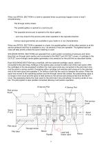
When any SPOOL SECTION in a bank is operated three occurrences happen (more or less*) simultaneously… The through centre closes. The parallel gallery is opened to a service port. The opposite service port is opened to the return gallery. …and vice versa for the service ports when operated in the opposite direction. Various spool geometries are available to give meter-in or out characteristics. When any SPOOL SECTION is operated in a bank, the parallel gallery in all the other sections is at the service pressure and flow is available to any / all sections if they are operated. The lightest load...
Open the catalog to page 7
General assembly instructions Keep it clean Cleanliness is the primary means of assuring long life and reliable function of all the components in an hydraulic system. When assembling or dismantling valves keep the work area and tools clean, cover up any components that are left unattended with a clean layer of plastic. Do not allow foreign material, chemicals or water to come into contact with components. If a used valve is to be dismantled for repair or modification drain all fluid from the assembly and plug all the ports. Clean the outside of the valve thoroughly with a non-solvent based wash...
Open the catalog to page 8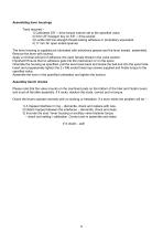
Assembling lever housings Tools required – 1) Calibrated 3/8” □ drive torque wrench set to the specified value. 2) 5mm AF hexagon key on 3/8” □ drive socket. 3) Loctite 222 low strength thread locking adhesive or proprietary equivalent. 4) 17 mm AF open ended spanner The lever housing is supplied pre lubricated with anhydrous grease and the lever loosely assembled. Remove the lever with locknut. Apply a minimal amount of adhesive into each female thread in the valve section. Important! Ensure that no adhesive gets into the mechanism or on the spool. Orientate the housing as specified, pull the...
Open the catalog to page 9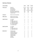
VALVE RANGE Performance Protection Relief valves Spools manual Spools solenoid Mechanisms Rated flow Port size Inlet Port size Service Port size Outlet Max pressure manual valves Max pressure Solenoid valves Load hold check Marine enviroment protection Relief valve direct acting Relief valve pilot operated D - Cylinder M - Motor A - Single acting 'A' port B - Single acting 'B' port K - Cylinder fine metering MF - otor fine metering 4 - 4th position float D - Cylinder M - Motor A - Single acting 'A' port B - Single acting 'B' port 3 position spring 3 position Detent 3 position spring/detent 3...
Open the catalog to page 10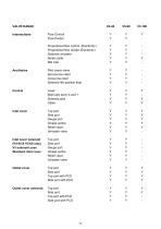
V4-40 V5-60 V3-100 Intersections Ancillaries Flow Control Y Y Proportional flow control (Electronic) Y Y Proportional flow divider (Electronic) Y Y Pilot check valve Y Y Service line relief Y Y Cross line relief Y Y Solenoid 4th position float Y Y Control Lever Multi axis lever X and + Solenoid pilot Cable Inlet cover Top port Side port Gauge port Closed centre Relief valve Unloader valve Inlet cover solenoid (V4-40 & V5-60 only) V3 solenoid uses Standard inlet cover Top port Side port Gauge port Closed centre Relief valve Unloader valve Outlet cover Top port Side port Top port with PCO Side...
Open the catalog to page 11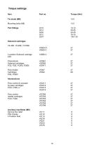
Item Tie studs (M8) Mounting bolts (M8) Port fittings 4 position Solenoid cartridge 4XX Proportional Solenoid cartridges FCE, FDE, FCEN, FDEN Flow divider Cartridges FDE, FDEN Intersections Flow control & unloader by-pass cartridges FCN, FC60, U Flow control needle cartridges FCN, FC60 Ancillary manifolds (M6) Service line relief Pilot checks 4 Position float
Open the catalog to page 12All Hydraulic Projects catalogs and brochures
 ML+40-8
3 Pages
 PR+ Brochure
3 Pages


Archived catalogs
 WINCH VALVE
1 Page
 HOSE REEL VALVE
2 Pages

- Boat pump
- Oil pump
- Positive-displacement pump
- Boat valve
- Nautical boat steering
- Hydraulic steering
- Gear pump
- Steering system cylinder
- Mechanical steering
- Piston pump
- Reversible pump
- Hydraulic system actuator
- Autopilot drive unit
- Linear actuator
- Hydraulic drive unit
- Hydraulic lifting system
- Boat hydraulic lifting system
- Hydraulic system drive unit
- Hydraulic actuator