- Catalogs
- Hemisphere GPS
- CRESCENT P102/P103 OEM BOARDS
CRESCENT P102/P103 OEM BOARDS
1 /50Pages

CRESCENT P102/P103 OEM BOARDS
1 /50Pages
Catalog excerpts

Cresent OEM Board Product Name Integrator Guide Quick Reference Guide
Open the catalog to page 1
This device complies with part 15 of the FCC Rules. Operation is subject to the following two conditions: (1) This device may not cause harmful interference, and (2) this device must accept any interference received, including interference that may cause undesired operation. Copyright Notice Copyright Hemisphere GNSS, Inc. (2013). All rights reserved. No part of this manual may be reproduced, transmitted, transcribed, stored in a retrieval system or translated into any language or computer language, in any form or by any means, electronic, mechanical, magnetic, optical, chemical, manual or otherwise,...
Open the catalog to page 2
Introduction . . . . . . . . . . . . . . . . . . . . . . . . . . . . . . 1 Crescent OEM Board Options . . . . . . . . . . . . . . . . . . . . . . . . . . . . . . 2 Product Overview . . . . . . . . . . . . . . . . . . . . . . . . . . . . . . . . . . . . . . . . 3 What’s Included . . . . . . . . . . . . . . . . . . . . . . . . . . . . . . . . . . . . . . . . . 3 Board Integration . . . . . . . . . . . . . . . . . . . . . . . . . . . . . . . . . . . . . . . . 4 Key Features . . . . . . . . . . . . . . . . . . . . . . . . . . . . . . . . . . . . . . . . . . . . 4 Message Interface . . . . . . . ....
Open the catalog to page 4
Frequently Asked Questions . . . . . . . . . . . . . . . . 23 Integration . . . . . . . . . . . . . . . . . . . . . . . . . . . . . . . . . . . . . . . . . . . . 24 Power, Communication, and Configuration . . . . . . . . . . . . . . . . . 25 GPS Reception and Performance . . . . . . . . . . . . . . . . . . . . . . . . . . 26 SBAS Reception and Performance . . . . . . . . . . . . . . . . . . . . . . . . . 27 External Corrections . . . . . . . . . . . . . . . . . . . . . . . . . . . . . . . . . . . . 28 Antenna Installation . . . . . . . . . . . . . . . . . . . . . . . . . . . . . . . . . . . ....
Open the catalog to page 5
Chapter 1: Introduction Crescent OEM Board Options Product Overview What's Included Board Integration Key Features Message Interface Using PocketMax to Communicate with the Crescent Crescent Integrator Guide 1 PN 875-0158-000 Rev D1
Open the catalog to page 6
This manual does not cover receiver operation, the PocketMax™ utility, or commands and messages (NMEA 0183, NMEA 2000® or HGPS proprietary). For information on these subjects refer to the Hemisphere GPS Technical Reference (go to www.hemispheregps.com and click the GPS Reference icon). Crescent OEM Board Options Table 1-1 lists the current Crescent® OEM board models. Table 1-1: Crescent board models Note: Throughout this manual, the Crescent OEM board is referred to simply as the Crescent. Crescent Integrator Guide 2 PN 875-0158-000 Rev D1
Open the catalog to page 7
Product Overview With its small form factor, low power consumption, and simple onboard firmware the Crescent is an ideal solution for integrators, offering scalability and expandability from GPS with SBAS to L1 GPS RTK. The Crescent is offered in two common industry form factors: • P100, P102, and P104 offer Hemisphere GPS' standard pinout configuration (34-pin) • P101 and P103 have a mechanical design compatible with popular aftermarket products (20-pin) See "Headers and Pinouts" on page 12 for information on the pinout configurations of each board. The reliable positioning performance...
Open the catalog to page 8
Board Integration Successful integration of the Crescent within a system requires electronics expertise that includes: • Power supply design • Serial port level translation • Reasonable radio frequency competency • An understanding of electromagnetic compatibility • Circuit design and layout The Crescent GPS engine is a low-level module intended for custom integration with the following general integration requirements: • Regulated power supply input (3.3 VDC ± 3%), 300 mA continuous • Low-level serial port (3.3 V CMOS) and USB port communications • Radio frequency (RF) input...
Open the catalog to page 9
Message Interface The Crescent uses a NMEA 0183 interface, allowing you to easily make configuration changes by sending text-type commands to the receiver. The Crescent also supports a selection of binary messages. There is a wider array of information available through the binary messages, plus binary messages are inherently more efficient with data. If the application has a requirement for raw measurement data, this information is available only in a binary format. For more information on NMEA 0183 commands and messages as well as binary messages refer to the Hemisphere GPS Technical Reference...
Open the catalog to page 10
Chapter 2: Board Overview Mechanical Layout Connectors Mounting Options Headers and Pinouts Signals Shielding Receiver Mounting Crescent Integrator Guide 7 PN 875-0158-000 Rev D1
Open the catalog to page 12
Chapter 2: Board Overview Mechanical Layout Figure 2-1 shows the mechanical layout for the Crescent P100/P102/P104 OEM boards and Figure 2-2 shows the mechanical layout for the Crescent P101/P103 OEM boards. Dimensions are in millimeters (inches) for both layouts. 6.8 mm (.27 in) Note: For older P100 boards this measurement is 5.9 mm (.23 in). Contact Hemisphere GPS Technical Support if you have any questions. Figure 2-1: Crescent P100/P102/P104 mechanical layout Crescent Integrator Guide
Open the catalog to page 13
Chapter 2: Board Overview Figure 2-2: Crescent P101/P103 mechanical layout Crescent Integrator Guide
Open the catalog to page 14
Chapter 2: Board Overview Connectors Table 2-1 describes the Crescent's connectors and mating connectors. You can use different compatible connectors; however, the requirements may be different. The antenna input impedance is 50 Q. Table 2-1: Crescent connectors Note: For the Samtec FTSH headers, '-01' indicates 0.120" posts and '-04' indicates 0.150" posts. Crescent Integrator Guide 10 PN 875-0158-000 Rev D1
Open the catalog to page 15
Chapter 2: Board Overview Mounting Options There are two options for mounting the Crescent: • Direct electrical connection method • Indirect electrical connection (cable) method Direct Electrical Connection Method Place an RF connector, heading connector, and mounting holes on the carrier board and then mount the Crescent on the standoffs and RF and header connectors. This method is very cost effective as it does not use cable assemblies to interface the Crescent. Note: Be aware of the GPS RF signals present on the carrier board and ensure the correct standoff height to avoid any flexual...
Open the catalog to page 16All Hemisphere GPS catalogs and brochures
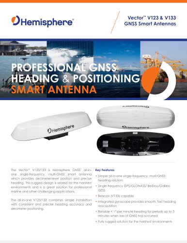 Vector™ V123 & V133
2 Pages
 VS1000
2 Pages
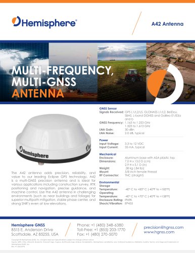 A42
A421 Page
 A43
A431 Page
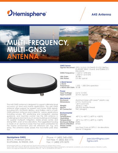 A45
A451 Page
Archived catalogs
 R330? GNSS RECEIVER
2 Pages
 S321
S3212 Pages
 Atlas Brochure
6 Pages
 HemisphereGNSS AtlasLink
2 Pages
 GNSS OEM Modules Brochure
2 Pages
 HemisphereGNSS V320
2 Pages
 S320? GNSS SURVEY RECEIVER
2 Pages
 HemisphereGNSS XF3
2 Pages
 A21? ANTENNA
1 Page
 A325™ GNSS Smart Antenna
2 Pages
 S321+ GNSS SMART ANTENNA
2 Pages
 A222™ Smart Antenna
29 Pages
 IRONVIEW CW400 DATA COLLECTOR
55 Pages
 A101 Smart Antenna
34 Pages
 A325
A32533 Pages
 POCKETMAX4
43 Pages
 S320 Product Brochure
6 Pages


- Boat antenna
- Radome antenna
- Ship antenna
- GPS antenna
- Inertial navigation system
- WiFi antenna
- Ship inertial navigation system
- Boat receiver
- Professional antenna
- IMU inertial navigation system
- GNSS antenna
- GNSS inertial navigation system
- IP66 antenna
- IP69K antenna
- GPS receiver
- High-accuracy inertial navigation system
- UHF antenna
- IP67 antenna
- Boat inertial navigation system
- GNSS receiver