


A325

A325
The A325 Smart Antenna is a portable GNSS solution designed for agricultural, marine, and GIS mapping applications. It features Hemisphere GNSS’ Eclipse multifrequency technology for fast startup and reacquisition, housed in a durable enclosure. The device supports dual-serial, CAN, and pulse output options, ensuring compatibility with various interfaces.
The A325 offers centimeter-level accuracy, enhanced GNSS performance with RTK and GLONASS, and long-range RTK baselines up to 50 km. It supports multiple communication protocols, including CAN, NMEA 0183, and NMEA 2000, and features Bluetooth for wireless data transfer. It operates on a wide voltage range and includes a 2D tilt sensor for offset corrections.
The A325 may include MFA software, allowing users to set positioning hierarchy based on differential sources, prioritizing RTK, followed by L-band, SBAS, Beacon, External RTCM, and Autonomous modes.
The A325 features ports and connections at the bottom, including a power/data port for external communication. It supports magnetic, surface, and pole mounts. Configuration can be done using default parameters or customized settings.
The A325 supports radar-simulated pulse output for ground speed measurement and various NMEA 2000 messages. It includes a single LED display indicating system status.
The guide includes troubleshooting tips and technical specifications. For assistance, users can contact their local dealer or Hemisphere GNSS technical support.
The A325 supports various NMEA 2000 messages on a CAN bus, including system time, attitude, position updates, and GNSS data.
- Mounting the A325: Ensure an unobstructed sky view, central mounting, and high positioning. Options include magnetic, surface, and pole mounts.
- Cable Routing: Avoid excessive heat, corrosive chemicals, and tension. Keep cables away from high voltage or RF noise sources.
The antenna accepts 7-36 VDC and requires a clean power supply. It uses a single cable for power and data, with reverse polarity protection.
The A325 can be configured via serial port using Hemisphere GNSS commands. Default parameters include DGPS applications and GPS message types.
The A325 tracks GPS satellites and uses differential corrections for accuracy. It supports automatic SBAS tracking.
Appendix A provides solutions for common issues like power failures and GPS lock issues, emphasizing checking power connections and antenna integrity.
- No SBAS: Check antenna cable integrity and sky view, verify application and settings, and ensure SBAS coverage.
- No GNSS Position: Verify sky view and application settings.
- No DGPS Position in External RTCM Mode: Verify baud rate and pinout connections.
- Non-DGPS Output: Ensure receiver authorization for RTK.
- GNSS Sensor: Supports GPS, GLONASS, and GALILEO, with 270 channels and an update rate of 10 Hz standard.
- Horizontal Accuracy: RTK accuracy of 10 mm+1 ppm (RMS).
- L-band DGNSS/HP/XP Sensor: Sensitivity of -130 dBm, with manual and automatic satellite selection.
- Communication: Supports RS-232, Bluetooth, CAN, NMEA 0183, NMEA 2000, and Hemisphere GNSS binary protocols.
- Power: Input voltage of 7-36 VDC, power consumption of <4.6 W.
- Environmental: Operating temperature from -40°C to +70°C, IP67 enclosure.
- Mechanical: Dimensions of 104.0 H x 145.0 D (mm), weight <558 g.
- Licensee is granted a non-transferable and non-exclusive license to use the Software embedded in a Product.
- Restrictions include not copying, modifying, or distributing the Software.
- Updates may be provided at Hemisphere's discretion.
- Licensee is responsible for data backups.
- Hemisphere owns all rights to the Software.
- Limited warranty for one year from purchase.
The agreement is governed by the laws of the State of Arizona.
To receive warranty service, the end purchaser must bring the product to a Hemisphere GNSS approved service center with proof of purchase. Contact Hemisphere GNSS for service center locations.
Catalog excerpts

Product Name A325 GNSS SmartGuide Quick Reference Antenna User Guide Part No.
Open the catalog to page 1
This device complies with part 15 of the FCC Rules. Operation is subject to the following two conditions: (1) This device may not cause harmful interference, and (2) this device must accept any interference received, including interference that may cause undesired operation. This product complies with the essential requirements and other relevant provisions of Directive 2014/53/EU. The declaration of conformity may be consulted at https://hemispheregnss.com/About-Us/Quality-Commitment. Copyright Notice Hemisphere GNSS Precision GNSS Applications Copyright © Hemisphere GNSS (2017). All rights...
Open the catalog to page 2
Notice to Customers Contact your local dealer for technical assistance. To find the authorized dealer near you: Hemisphere GNSS 4110 9th Street S.E. Calgary, Alberta, Canada T2G 3C4 Phone: 403259-3311 Fax: 403-259-8866 [email protected] www.hgnss.com Technical Support If you need to contact Hemisphere GNSS Technical Support: Hemisphere GNSS 8515 East Anderson Drive, Suite A Scottsdale, Arizona, US 85255 Phone: 480-348-6380 Fax: 480-270-5070 [email protected] Documentation Feedback Hemisphere GNSS is committed to the quality and continuous improvement of our products and services. We urge...
Open the catalog to page 3
Chapter 1: Introducing the A325 Smart Antenna A325 Overview Key Features Multi-Function Application (MFA) Software Parts List Product Support A325 GNSS Smart Antenna User Guide 1 PN 875-0318-000 Rev D2
Open the catalog to page 5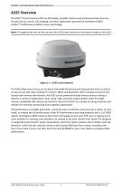
Chapter 1: Introducing the A325 Smart Antenna A325 Overview The A325™ Smart Antenna offers an affordable, portable solution with professional level accuracy for agricultural, marine, GIS mapping, and other applications powered by Hemisphere GNSS’ Eclipse™ multifrequency GNSS receiver technology. Note: Throughout the rest of this manual, the A325 Smart Antenna is referred to simply as the A325. Figure 1-1: A325 smart antenna The A325 allows you to focus on the job at hand with fast startup and reacquisition times as well as an easy-to-see LED status indicator for power, GNSS, and Bluetooth. With...
Open the catalog to page 6
Chapter 1: Introducing the A325 Smart Antenna Key Features Key features of the A325 include: • Centimeter-level accuracy using Eclipse technology in a rugged, all-in-one enclosure • Improved GNSS performance—particularly with RTK and GLONASS applications—through the implementation of SureTrack technology • Long range RTK baselines of up to 50 km • Very fast RTK fix and reacquisition times • Supports CAN, NMEA 0183, NMEA 2000*, and binary for communication with external devices *requires NMEA certification • Bluetooth' capability for wireless datatransfer • Wide operating voltage range of 7-36...
Open the catalog to page 7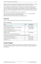
Chapter 1: Introducing the A325 Smart Antenna becomes unusable, the next mode will be selected (for example, L-band DGPS, or Beacon or External RTCM). Finally, if no correction signals are available, the device defaults to Autonomous. You can include or exclude specific sources. For example, you can exclude sources that you do not want your device to use, such as if you want to use only beacon. If you do not exclude the other sources your device may use SBAS instead. Another example is if you want to exclude L-band (when you do not have an L-band subscription) to conserve power. You include and...
Open the catalog to page 8
Chapter 2: Installing the A325 Ports and Connections Communication Mounting the A325 Powering the A325 Connecting to External Devices Default Parameters Configuring the A325 A325 GNSS Smart Antenna User Guide 5 PN 875-0318-000 Rev D2
Open the catalog to page 9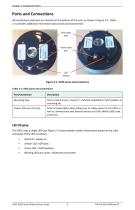
Ports and Connections All connections and ports are located on the bottom of the unit, as shown in Figure 2-1. Table 2-1 provides additional information about each port/connection. Mounting hole Power/data port Figure 2-1: A325 ports and connectors Table 2-1: A325 ports and connections LED Display The A325 uses a single LED (see Figure 2-1) that provides system information based on the color and pulse of the LED as follows: • Red LED = power on • Amber LED = GPS lock • Green LED = DGPS position • Blinking LED (any color) = Bluetooth connected A325 GNSS Smart Antenna User Guide 6 PN 875-0318-000...
Open the catalog to page 10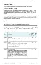
Communication The A325 supports radar-simulated pulse output and various NMEA 2000 messages. Radar-Simulated Pulse Output The radar-simulated pulse output provides accurate ground speed. The A325 uses pin 12 for the speed out pin. Pin 12 will output a square wave with a 50% duty cycle and the frequency of the square wave varies directly with speed. 94 Hz represents a speed of 1 m/sec (or 28.65 pulse/foot traveled). Note: Pin 12 does not have any form of isolation or surge protection. Hemisphere GNSS strongly recommends that you incorporate some form of isolation circuitry into your supporting...
Open the catalog to page 11
Table 2-2: Transmitted NMEA 2000 messages (continued') A325 GNSS Smart Antenna User Guide 8 PN 875-0318-000 Rev D2
Open the catalog to page 12
Mounting the A325 This section provides information on where to mount your antenna and the different mounting options available. Selecting the Proper Antenna Location Proper antenna placement is critical to positioning accuracy. To select the proper antenna location: • Place the antenna with an unobstructed view of the sky. An obstructed view of the sky may impair system performance. The GPS engine computes a position based on measurements from each satellite to the internal GPS receiver. • Mount the antenna on, or as close as possible to, the center of your point of measurement. For example,...
Open the catalog to page 13
Magnetic Mount The magnetic mount can be screwed into the bottom of the A325 and mounts to metal surfaces. A metal disc and foam adhesive are included with each magnetic mount. Use the foam adhesive to bond the metal disc to the desired mounting location if there are no metal surfaces. To mount the A325 using the magnetic mount: 1. Clean and dry the surface where you will attach the metal disc. Remove the backing from one side of the foam adhesive and press the adhesive onto the mounting surface. Remove the backing from the other side of the foam adhesive and press the metal disc onto the mounting...
Open the catalog to page 14All Hemisphere GPS catalogs and brochures
 Vector™ V123 & V133
2 Pages
 VS1000
2 Pages
 A42
A421 Page
 A43
A431 Page
 A45
A451 Page
Archived catalogs
 R330? GNSS RECEIVER
2 Pages
 S321
S3212 Pages
 Atlas Brochure
6 Pages
 HemisphereGNSS AtlasLink
2 Pages
 GNSS OEM Modules Brochure
2 Pages
 HemisphereGNSS V320
2 Pages
 S320? GNSS SURVEY RECEIVER
2 Pages
 HemisphereGNSS XF3
2 Pages
 A21? ANTENNA
1 Page
 A325™ GNSS Smart Antenna
2 Pages
 S321+ GNSS SMART ANTENNA
2 Pages
 A222™ Smart Antenna
29 Pages
 CRESCENT P102/P103 OEM BOARDS
50 Pages
 IRONVIEW CW400 DATA COLLECTOR
55 Pages
 A101 Smart Antenna
34 Pages
 POCKETMAX4
43 Pages
 S320 Product Brochure
6 Pages


- Boat antenna
- Radome antenna
- Ship antenna
- GPS antenna
- Inertial navigation system
- WiFi antenna
- Ship inertial navigation system
- Boat receiver
- Professional antenna
- IMU inertial navigation system
- GNSS antenna
- GNSS inertial navigation system
- IP66 antenna
- IP69K antenna
- High-accuracy inertial navigation system
- UHF antenna
- IP67 antenna
- Boat inertial navigation system