
- Catalogs
- GH Cranes & Components
- End carriages


End carriages

End carriages
Overview
This document provides detailed technical specifications, component descriptions, and dimensional data for crane components, focusing on end carriages, wheels, gearboxes, and electrical components used in single and double girder cranes, including underslung and gantry crane configurations.
1. Crane Components and End Carriages
The document lists various end carriage models identified by wheel diameters (e.g., Ø125-VB1, Ø160-VB2, Ø250-VC, Ø315-VC, Ø400-VD, Ø500-VD/VE) and their corresponding capacities and dimensions. It distinguishes between single girder and double girder cranes, providing wheel base measurements, spans, and capacities in tonnes (Tn).
Key parameters include wheel diameter, wheel base, span, and capacity. End carriages are available in welded (S), articulated (A), single girder (M), and double girder (B) types. Dimensions such as L1, L2, L3, L4, e1, e2, B, H1, H2, and H are specified for each model, critical for installation and compatibility.
2. Wheel Selection and Specifications
The wheel selection chart provides guidance on choosing wheels based on span, wheel base, and capacity. Wheel diameters range from 125 mm to 630 mm, with corresponding load capacities and speeds. Wheels feature double flanges and mounted bearings, designed for smooth acceleration and braking with minimal noise.
Wheel heads for gantry cranes are detailed with maximum admissible wheel loads according to FEM/UNE M4 standards, considering rail width and quality (minimum S355 steel). Different rail types such as Burbach, curved, and square rails are referenced with dimensional formulas.
3. Gearboxes and Motor Specifications
The document describes three-stage and four-stage motor-gearboxes specially designed for cross travel and long travel motions. Gearboxes are directly connected to wheels via splined shafts, ensuring gradual acceleration and smooth braking.
Motor power ratings range from 0.4 kW to 7.5 kW, with various motor types and gearbox models (e.g., VB1-60, VB2-60, VC-85, VD-110, VE-110). Weight and dimensional data for gearboxes and motors are provided, essential for integration into crane systems.
4. End Carriage Dimensions and Weights
Detailed tables list dimensions (A1, A2, A3, A4, A5, A7, A8, etc.) and weights for end carriages across different models and girder types. Minimum dimensions and base measurements (dimension B) are highlighted, along with trolley span (dimension A14).
Weights vary significantly depending on the model and configuration, with separate data for single and double girder cranes. This information is critical for structural design and load calculations.
5. Electrical Components and Accessories
The document enumerates electrical components and accessories integral to crane operation, including:
- Hoist limit switch
- Load limit device
- Pendant plug-in connector
- Cross travel and long travel limit switches and actuators
- Supports for power feed systems and cable protection
- Motor plug-in connectors
- Towing arm and cable trolleys
- Remote control and control cabinets (hoist and long travel)
- Structural supports such as girder and profile supports, ladder support
These components ensure safe and efficient crane operation, with emphasis on limit controls and power management.
6. Boogies and Wheel Heads for Gantry Cranes
Specifications for boogies with wheel diameters ranging from 315 mm to 630 mm are provided, including weight, span, and admissible wheel loads. Weld-on wheel heads are detailed with dimensions and load capacities, designed for various rail widths and types.
The document includes dimensional data for wheel heads and boogies, supporting selection and maintenance of gantry crane components.
Critical Information and Best Practices
- Wheel diameter selection depends on speed, duty cycle, and rail width; final diameter must be confirmed accordingly.
- End carriages with dimension A1 less than 2100 mm are supplied as loose items, indicating special handling or installation requirements.
- Load capacities and wheel loads comply with FEM/UNE M4 standards, ensuring safety and reliability.
- Motor-gearbox assemblies are designed for smooth operation with minimal noise and gradual acceleration.
- Electrical components include multiple limit switches and safety devices to prevent over-travel and overload conditions.
Conclusion
This technical document serves as a comprehensive reference for selecting, specifying, and installing crane components, particularly end carriages, wheels, gearboxes, and electrical systems. It provides essential dimensional data, load capacities, and operational parameters to ensure compatibility, safety, and performance in crane applications.
Catalog excerpts

END CARRIAGES CRANE COMPONENTS
Open the catalog to page 1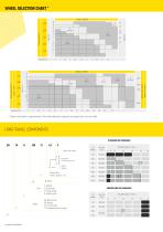
WHEEL SELECTION CHART * SINGLE GIRDER 4200 DOUBLE GIRDER * Given information is approximate. Final wheel diameter depends on speed, duty and rail width. LONG TRAVEL COMPONENTS STANDARD END CARRIAGES Speed Speeds Wheel base (00 for types S, T, A) S: Welded A: Articulated M: Single girder B: Double girder CB: Wheel head BG: Boogie TA: End carriage TS: Underslung end carriage Possible speeds in m/min. Possible speeds in m/min. High speed Precission speed 1/4 Useful rail width
Open the catalog to page 2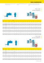
TRAVEL GEAREDMOTORS Gradual acceleration, smooth brakes, all with minimum noise. Specially designed by GH for use on cross travel and long travel motions. Travel wheels with double flanges with mounted bearings. Drive to the wheels is direct via splined shaft. THREE STAGE MOTOR-GEARBOXES L3 Motor type Gearbox type FOUR STAGE MOTOR-GEARBOXES D Motor type
Open the catalog to page 3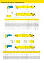
END CARRIAGES FOR SINGLE AND DOUBLE GIRDER CRANES 200 (Minimum dimension) Double Girder Single Girder Single Girder Double Girder * Dimension "B" corresponds to the measurement of the base of the girder. ** Dimension A14 corresponds to the span of the trolley. 200 (Minimum dimension) Single Girder * Dimension "B" corresponds to the measurement of the base of the girder. ** Dimension A14 corresponds to the span of the trolley. GH CRANES & COMPONENTS Double Girder Single Girder Double Girder
Open the catalog to page 4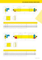
END CARRIAGES FOR DOUBLE GIRDER CRANES A2 (Minimum dimension) * Dimension "B" corresponds to the measurement of the base of the girder. ** Dimension A14 corresponds to the span of the trolley. (Minimum dimension) * Dimension "B" corresponds to the measurement of the base of the girder. ** Dimension A14 corresponds to the span of the trolley.
Open the catalog to page 5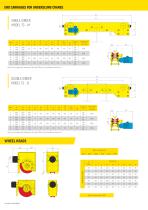
END CARRIAGES FOR UNDERSLUNG CRANES A2 A1 SINGLE GIRDER MODEL TS - M Average admissible wheel load per 2 wheels (daN) Note: End carriages with dimension A1 less than 2100 are only available as loose item. DOUBLE GIRDER MODEL TS - B Average admissible wheel load per 2 wheels (daN) Note: End carriages with dimension A1 less than 2100 are only available as loose item. Weld-on wheel head Ø160 Welded wheel-head Weld-on wheel head Ø 630
Open the catalog to page 6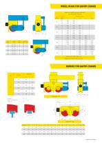
WHEEL HEADS FOR GANTRY CRANES Maximum admissible wheel loads GGG70 (daN) Acc. with FEM/UNE M4 group Ø Wheel Gearbox type Cross travel speed in m/min Loads for ratio Rmin / Rmax = 0.35 Rolling track minimum quality S355 (St52) BOOGIES FOR GANTRY CRANES Dimensions Rail Type Burbach rail: Curved rail wheel head: Square rail:
Open the catalog to page 7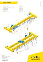
Hoist limit switch. Load limit device. Pendant plug-in connector. Cross travel limit switch actuator. Supports for cross travel and pendant power feed systems. Motor plug-in connectors. Towing arm. Cross travel limit switch. Long travel limit switch. Long travel limit switch actuator. Current collector arm. Festoon cable protection supports. 13. Cable clips. 14. Profile connection. 15. Sliding support. 16. End limit. 17. Cable trolleys. 18. Remote control. 19. Girder support. 20. Profile support. 21. Long travel cabinet. 21A. Hoist cabinet. 22. Ladder support. 23. Trolley rail. 6 7 Sede Central...
Open the catalog to page 8All GH Cranes & Components catalogs and brochures
 GH-NEWS-23
40 Pages
 GH-NEWS-24
42 Pages
 Electric Chain Hoists
6 Pages
 GH NEWS 24
42 Pages
 GH NEWS 23
40 Pages
 Ex Solutions
8 Pages
 Trade Brochure Fairs USA
2 Pages
 GH Corporate catalog
87 Pages
 GH catalog accessories
114 Pages
 MARINE SOLUTIONS
14 Pages
 INDUSTRIAL SOLUTIONS
14 Pages
 GH Real Time
2 Pages
 Corebox
1 Page
 ATV+AntiSway
1 Page
 Sell sheet GHE17
2 Pages
 Sell sheet GHB11 2021
2 Pages
 Sell sheet GHD13 2021
2 Pages
 Sell sheet GHA12 2021
2 Pages
 STANDARD CRANES
32 Pages
 Transfer carts
8 Pages
 GH´NEWS 22
28 Pages
 Open winch
12 Pages
 Components
12 Pages
 Standard kit components
6 Pages
 Waste-to-Energy cranes
12 Pages
 GHE17
GHE172 Pages
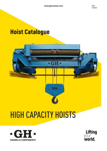 High capacity hoists
8 Pages
 GH Motion
18 Pages
 GH´NEWS 21
32 Pages
 GH´NEWS 20
28 Pages
 GH´NEWS 19
71 Pages
 GH´NEWS 18
11 Pages
 GH´NEWS 17
5 Pages
 Shipyard cranes
20 Pages
 Electric wire rope hoist
4 Pages
 Coreplus Synchro
1 Page
 Coreplus Stability
1 Page
 Lifting your world
24 Pages
 Automotive marine gantries
6 Pages
 Mailing kits
2 Pages
 Gantry cranes
12 Pages
 Automotive
16 Pages
 Aeronautic
16 Pages
 Pulp and paper industry
12 Pages
 Waste-to-Energy cranes (zh)
16 Pages
 Jib cranes
8 Pages


Archived catalogs
 Ponts roulants
13 Pages
 Bridge cranes
12 Pages
 Gantry cranes
12 Pages
 Bridge cranes
12 Pages
 Hoists
8 Pages


