
- Catalogs
- Gems Sensors
- J-Valves_05-16-2011opt


J-Valves_05-16-2011opt

J-Valves_05-16-2011opt
Gems Sensors specializes in custom fluidic systems, integrating miniature and subminiature solenoid valves for industries such as medical, biotech, automotive, and industrial equipment. These valves are designed to meet specific application requirements, offering a wide range of construction and performance options.
- Cryogenic Valves: Suitable for media temperatures as low as -320°F, ideal for liquid nitrogen and carbon dioxide.
- Isolation Valves: Feature isolation diaphragms for high-purity and aggressive media applications.
- General Purpose Valves: Available in 2- and 3-way configurations, customizable for specific applications.
The document provides formulas for calculating the valve flow coefficient (CV) for both liquid and gas applications. For liquids, CV depends on the pressure differential, while for gases, it also considers temperature due to compressibility.
- Calculate CV: Determine the valve flow coefficient using pressure differential, flow rate, specific gravity, and temperature (for gases).
- Identify Valve Function: Choose the valve function based on application needs, considering the CV for either the body or stop orifice.
- Select Valve Series: Use charts to select the appropriate valve series based on MOPD, CV, and other specifications.
- Configure Valve: Finalize design by selecting materials, coil construction, port configuration, manifold assembly, and voltage.
The document includes detailed specifications for various valve series, including power ratings, orifice sizes, and MOPD. It also provides guidance on ordering and customizing valves to meet specific application requirements.
For assistance, contact Gems Sensors at 800-378-1600 or [email protected]. The company offers support for valve selection, customization, and integration into fluidic systems.
The document outlines the specifications for different solenoid valve series, including power ratings, orifice sizes, maximum operating pressure differential (MOPD), and flow coefficients (CV). It details the construction materials available for the valve bodies, such as stainless steel, acetal, and brass, and the options for plunger seal and O-ring materials.
A comprehensive guide is provided on how to construct a product code for ordering. This includes selecting the primary prefix, coil construction, body material, plunger seal material, O-ring material, body port configuration, voltage, and additional options. Standard selections are indicated, which are used unless otherwise specified.
The document describes various valve configurations, including 2-way normally closed (N.C.), 2-way normally open (N.O.), 3-way N.C., 3-way N.O., multi-purpose, and directional control valves. Each configuration is associated with specific power ratings and operational parameters.
Typical applications for the valves are listed, highlighting their use in medical equipment, laboratory equipment, water purification systems, and industrial applications. The choice of materials and configurations allows for customization to meet specific environmental and operational requirements.
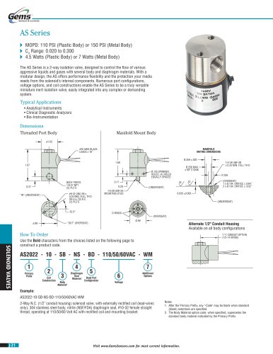
Detailed dimensions and mounting instructions are provided for different valve body types, including threaded port bodies and manifold mount bodies. This section ensures proper installation and integration into existing systems.
- Body materials include 303, 304, 316, and 430F stainless steel, as well as brass.
- Plunger seal materials include Nitrile, EPR, Viton, and PTFE, among others.
- O-ring materials are available in Nitrile, EPR, Neoprene, and Viton.
- Standard port configurations include 1/8-27 NPT and 1/4-18 NPT female threads.
- Additional configurations include manifold mounts and various bottom port options.
- Valves can be configured for DC or AC voltages, with specific coil constructions available for different applications.
- Coil options include tape-wrapped, encapsulated, and over-molded coils in various classes (B, F, H).
- Options for quiet operation, oxygen cleaning, and vacuum applications are available.
- Mounting brackets, yokes, and other accessories can be specified.
The document includes tables with technical data such as orifice size, maximum operating pressure differential (MOPD), and CV values for different valve configurations. It also provides dimensions and manifold mating dimensions for the valves.
The valves offer various additional options, including mounting brackets, PTFE coated plungers, quiet operation, and cleaning for oxygen use. The document also mentions the availability of alternate conduit housing for all body configurations.
- Simplified fluidic systems with fewer leak paths.
- Reduction in mounting hardware and fittings.
- Compact design with multiple valve configurations for precise flow control.
- Reduced labor for OEMs and easy maintenance.
Purchasing a complete fluidic system from Gems offers several advantages, including:
- 100% tested systems ready for installation.
- Reduced supplier requirements and assembly of third-party parts.
- Minimized potential leak points by eliminating tubing and fittings.
- Integration of multiple valve types, fittings, electrical terminations, sensors, and more.
The document provides a checklist for specifying valve configurations, including:
- Flow requirements and pressure specifications.
- Material choices for body, plunger seal, and O-ring.
- Electrical and coil requirements.
- Body configuration and environmental considerations.
Catalog excerpts

. Sensors & Controls Miniature and Subminiature Solenoid Valves Gems specializes in made-to-order fluidic systems, and a major segment of that activity includes the integration of miniature solenoid valves and manifold assemblies. Our miniature and subminiature solenoid valves are utilized in solutions that serve industries ranging from medical and biotech to automotive and industrial equipment. Gems solenoid valves are designed to your specifications for each unique application. Each series offers a broad range of construction/performance options to build an endless array of configurations—too many to list in this catalog. From custom coils and manifolds to exotic materials and flow characteristics, there is very little that we cannot accomplish. Whether pneumatic or liquid, cryogenic or high temperature, vacuum or high-pressure, we partner with you to identify, create, and produce the best possible fluidic solution. If at any time, you have a question or simply want to give us your requirements and have Gems Sensor and Controls design your valve or system, please contact us by phone at 800-378-1600 or email us at [email protected]. Contents_Page Start An application data sheet (ADS), located on page J-40, will help you select performance criteria and options. Fax it directly to a Gems Valve Engineer at 860-747-4244 or configure your valve online for RFQ at www.gemssensors.com. General Purpose Valves A broad range of 2- and 3-way solenoid valves in both miniature and subminiature sizes. A wide selection of configuration options allows easy customization to match specific application requirements. Isolation Valves Isolation diaphragms protect media and moving parts alike. Ideal for high-purity Cryogenic Valves These valves provide reliable service to (-196°C). Ideal for liquid Nitrogen and Visit www.GemsSensors.com for most current information.
Open the catalog to page 1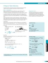
INTRODUCTION 4 Steps to Valve Selection The steps described in this section will help you identify the performance criteria needed to meet your application requirements and select the right valve. Step 1 – Calculating CV Begin by calculating the valve flow coefficient (CV) using: operating pressure differential; flow rate for your application; Specific Gravity; and in some circumstances, temperature. If you already know your CV please go directly to Step 2. CV combines the effects of all flow restrictions in the valve into a single number. CV represents the quantity of water, at 68°F and in gallons...
Open the catalog to page 2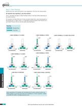
Sensors & Controls Step 2 - Valve Function Identify how your valve will function in your application. Pick from the choices below. An important note regarding Cv and valve function: The Cv calculated will apply to either the Body Orifice or the Stop Orifice depending on For example, the Stop Orifice for a 3-way normally closed valve, when de-energized, is the exhaust port. In other words, Cv is calculated using the specific Inlet Pressure (P1) and Outlet Pressure (P2) for the flow paths described below. Blocked Flow Free Flow DE-ENERGIZED ENERGIZED DE-ENERGIZED ENERGIZED 2-WAY NORMALLY CLOSED...
Open the catalog to page 3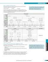
Step 3 - Identify Your Valve Series Select possible valve series candidate using the overview charts below. Begin by choosing the category for your application: • General Purpose «Isolation «Cryogénie Using the charts, select maximum operating pressure differential (MOPD), the CY, function, and additional specifications needed for your application to select possible valve series. The detailed performance specs for each series are located on the corresponding pages listed on the chart. •Consult factory for higher MOPD Step 4 - Make Your Selection and Configure Your Valve Complete your valve design...
Open the catalog to page 4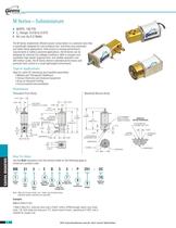
. Sensors & Controls The M Series implements efficient power conservation in a solenoid valve that is specifically designed for sub-miniature two- and three-way pneumatic and select liquid applications. Field proven to exceed performance requirements in battery-powered applications, the M Series can be designed for extreme low wattage conditions. With a compact size, consistent high-speed response time, and reliable operation over 200 million cycles, the M Series delivers extended performance and precision flow control in a small lightweight environment. Typical Applications Ideal for inline...
Open the catalog to page 5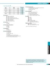
Part Prefix Table© 30 =3-Way normally closed (free vent) 31 =3-Way normally closed (line connection) @ Plunger Seal / O-Ring Material (6) Body Port Configuration 4 = Manifold mount, #10-32 UNF-2A stud* 5 =#10-32 UNF-2B female thread (180° apart only) 6 = 1/8"-27 NPT ports (180° apart only) GENERAL PURPOSE © Stop Port Configuration 0 = No barb (Standard for 2-way NC & 3-way free vent) Q = Quick connect 0.110 spade W_= Lead-wires (Specify length in inches) _VAC =AC Rectified 2-watt coil only (specify voltage, lead-wires only) ©Additional Options t Teflon® o-ring not suitable for manifold mount....
Open the catalog to page 6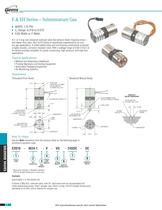
. Sensors & Controls A 2- or 3-way sub-miniature solenoid valve that delivers faster response times— and higher flow rates, the E & EH Series is specifically engineered for air and dry gas applications. A nickel-plated body and coil housing construction produces a highly durable, corrosion resistant valve. With a wattage range of 0.65-2 the E & EH Series provides versatility for power conserving, high pressure, and high flow Typical Applications • Medical and Respiratory Healthcare • Printing Machinery and Sorting Equipment •Automated Packaging Equipment Threaded Port Body BODY PORTS STOP PORT...
Open the catalog to page 7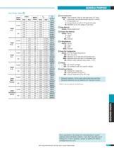
GENERAL PURPOSE Part Prefix Table© (blank) = Tape-wrapped, Class-B, with lead-wires (12"long)* W_= Lead-wires, non-standard length (specify in inches) 5 = Encapsulated coil with 0.110 spade terminals 10 = Rectified coil for AC voltage (2 watt only) ©Body Material (blank) = Nickel-plated brass* ©Plunger Seal Material ©O-Ring Material ©Body Port Configuration (blank) =#10-32 straight thread ports* MM = Manifold mount with #10-32 threaded stud* MM2 = Manifold mount with M5 x 0.8 threaded studi BO = Bottom under-seat port (max orifice = 1/16") _VAC =AC rectified 2-watt only (specify voltage) ©Additional...
Open the catalog to page 8All Gems Sensors catalogs and brochures
 D-Cryo Series Solenoid Valve
2 Pages
 B-Cryo Series Solenoid Valve
2 Pages
 AS Series Solenoid Valve
2 Pages
 BS Series Solenoid Valve
2 Pages
 KM/KL Series Solenoid Valve
4 Pages
 KV/KW Series Solenoid Valve
2 Pages
 PM/PL Series
2 Pages
 Gems Master Catalog Product
406 Pages
 3600 Series
4 Pages
 3800 Series
2 Pages
 3500 Series
4 Pages
 F Series
4 Pages
 Appendix and Glossary
13 Pages
 Pressure Transducers
67 Pages
 Pressure Switches
30 Pages
 Flow Switches
26 Pages
 Warrick Conductivity Sensors
29 Pages
 Level Sensors Continuous
33 Pages
 Level Indicators Visual
27 Pages
 Level Switches Multi-Point
26 Pages
 Warrick_Conductivity_Sensors
29 Pages
 Level_Sensors_Continuous-
33 Pages
 Level_Indicators_Visual
27 Pages
 Level Switches Single Point
43 Pages
 Level_Switches_Mult-Point
26 Pages
 Solenoid Valves
40 Pages
 Flow Sensors
13 Pages
 Electronic_Products-
13 Pages
 Proximity_Switches-
5 Pages
 Flow_Switches
24 Pages
 Pressure_Switches
28 Pages
 Pressure_Transducers-5-16-2011
44 Pages
 Gems_ProdOverview_2008_Opt_Print
12 Pages
 SemiconBroch
8 Pages
 FS-380P Series
2 Pages


