Catalog excerpts
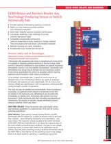
SOLID STATE RELAYS AND BARRIERS GEMS Relays and Barriers Render Any Non-Voltage Producing Sensor or Switch Intrinsically Safe ► Provide method of eliminating explosive conditions ► Rapid, arc-free response provides positive, non-mechanical operation ► Solid-state reliability assures consistent performance ► Low-power switching; a few milliamps of current controls high-power loads ► Completely encapsulated construction Units are impervious to dust, moisture or foreign material They are tamper-proof and shock- and vibration-resistant ► Modular housings for easier installation ► Exceptionally long, trouble-free service life Intrinsic Safety and its Advantages. Instrument Society of American Specification ISA-RP12.2 Defining Intrinsically Safe Equipment: "Intrinsically safe equipment and wiring is equipment and wiring which is incapable of releasing sufficient electrical or thermal energy under normal or abnormal conditions to cause ignition of a specific hazardous atmospheric mixture in its most ignited concentration. Intrinsically safe terminations and wiring may be brought into any hazardous location of any Group classification for which it is accepted without requiring explosion-proof housing or other means of protection." To be certified "intrinsically safe," a device or circuit must be so designed that no two simultaneous failures can cause an explosion. Intrinsically safe systems are more dependable. The I.S. circuit must function reliably per specifications, with no explosions, during and after cycling through a number of operations. The units can also be installed more conveniently. Since no explosion is possible, no explosion-proof conduit or enclosures of any kind are needed in the hazardous area. Maintenance can be performed immediately as needed. And, intrinsically safe systems are more economical. Costly enclosures with their mounting requirements are unnecessary. No purging is required, thereby eliminating blowers, pressure switches, timers and relays. SAFE-PAK® RELAYS: These intrinsically safe units amplify sensor load-handling capabilities in a wide diversity of AC and DC control switching applications. Zener Barriers: These passive, energy-limiting devices, provide intrinsically safe DC outputs for a variety of sensors such as level and flow switches.. .level indicating transducers and transmitters.. .and many others. The maximum energy possible at the switch terminals of the SAFE-PAK and Zener Barriers is far below the explosive point of the most volatile surrounding gas conditions. The type of non-voltage- producing switch or sensor best suited for the application can be utilized, since the entire switching circuit is rendered intrinsically safe by the SAFE-PAK or Zener Barrier. As the switching circuit is low voltage, there is no shock hazard to operating or maintenance personnel. Visit www.GemsSensors.com for most current information.
Open the catalog to page 1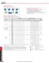
. Sensors & Controls Typical Applications Switches Located in Hazardous Areas Important points to remember when selecting Zener Barriers and Safe Pak® : • The maximum input voltage rating of the barrier must be higher than your power supply. (i.e., a 24 VDC supply would require a 30 V barrier.) • Make sure the barrier is rated for your hazardous area class, Intrinsic Safety Approvals - Safe-Pak® Relays and Zener Barriers 1. Certified intrinsically safe under MSHA certification No. 1662 for use on permissible equipment. 2. Zener Barrier models, Part Numbers 54801, 54803, 54805, 54806;...
Open the catalog to page 2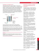
SAFE-PAK and Zener Barrier units are installed in a safe area and connected to the sensor in a hazardous location...no explosion-proof or protective housings of any kind are needed. Units install singly, in any position...or can be grouped on a common, earth-grounded plate with mounting tabs to provide electrical grounding. No. 6-32 threaded electrical terminals are conveniently placed atop the unit housings. Barriers and relays may be grouped on a common, earth-grounded mounting plate. Intrinsically safe sensor wiring must be separated from non-intrinsically-safe input wiring in separate...
Open the catalog to page 3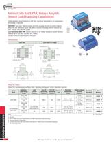
. Sensors & Controls Intrinsically SAFE-PAK® Relays Amplify Sensor Load-Handling Capabilities Costly explosion-proof enclosures with their mounting requirements are unnecessary. SAFE-PAK: Less than 100 microamps at 9 VDC actuates the unit to control loads to 5A at 120 VAC. Resistive (up to 100,000Q ) or short-circuiting sensors operate the Low Sensitivity SAFE-PAK: Sensor closures up to 1000Q resistance control resistive See table on Page L-2 for specific approval information Select Part Number based on Relay Style, Operating Voltage and Switch Operation required. 3. All AC voltage and...
Open the catalog to page 4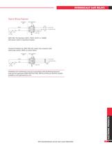
3 RED N.O. DRY OR N.C. DRY 2 1 RESISTOR (–) 3 BLACK 2 1 FUSE* DC POWER SUPPLY ANNUNC. (+) 2 CONDUCTOR CABLE intrinsically safe relays SIGNAL RETURN BARRIER Typical Wiring Diagrams HAZARDOUS AREA NON-HAZARDOUS AREA FUSE BLACK RED LOAD N.O. DRY OR N.C. DRY HOT VAC NEUTRAL VAC FUSE SAFE-PAK SAFE-PAK, Part Numbers 25872, 25873, 64101 or 144600 with sensor switch in hazardous location. Transient Protection for SAFE-PAK (AC Loads) Use a properly sized metal oxide varistor (MOV) as shown below. HAZARDOUS AREA NON-HAZARDOUS AREA BLACK HOT VAC NEUTRAL VAC RED N.O. DRY OR N.C. DRY SAFE-PAK LOAD...
Open the catalog to page 5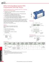
. Sensors & Controls Define Switching Mode Anytime With Programmable SAFE-PAK® Relays Provide normally open (N.O.), normally closed (N.C.) or latching output with variable time delays ► Designed for use with switches or sensors monitoring flow, ► They render non-voltage-producing sensors intrinsically safe for operation in potentially hazardous areas ► Streamlined housing suited for group-mounting on a common earth-grounded plate for multiple installation ► UL recognized, FM, CSA and evaluated by MSHA Operations such as normally open, normally closed or latching are programmed into these...
Open the catalog to page 6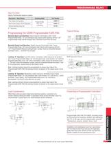
programmable relays How To Order Specify Part Number based on output. Description – Hybrid Relay Switching Mode Triac Output, AC Operation Part Number 54820 Programmable, N.O., N.C., or latching Reed Switch Output, AC/DC Operation Optional Rail Mounting Clip 54825 61783 – Stock Items. Typical Wiring Programming the GEMS Programmable SAFE-PAK Normally Open Load Operation: Switch closure to terminals 5 and 7 turns Programmable Relay “on” and energizes load. Same switch opening will turn “off” Programmable Relay and de-energize load. Terminals 6 and 8 are not used. SENSOR SWITCH 4 JUMPER Note:...
Open the catalog to page 7All Gems Sensors catalogs and brochures
-
D-Cryo Series Solenoid Valve
2 Pages
-
B-Cryo Series Solenoid Valve
2 Pages
-
AS Series Solenoid Valve
2 Pages
-
BS Series Solenoid Valve
2 Pages
-
KM/KL Series Solenoid Valve
4 Pages
-
KV/KW Series Solenoid Valve
2 Pages
-
PM/PL Series
2 Pages
-
Gems Master Catalog Product
406 Pages
-
3600 Series
4 Pages
-
3800 Series
2 Pages
-
3500 Series
4 Pages
-
F Series
4 Pages
-
Appendix and Glossary
13 Pages
-
Pressure Transducers
67 Pages
-
Pressure Switches
30 Pages
-
Flow Switches
26 Pages
-
Warrick Conductivity Sensors
29 Pages
-
Level Sensors Continuous
33 Pages
-
Level Indicators Visual
27 Pages
-
Level Switches Multi-Point
26 Pages
-
Warrick_Conductivity_Sensors
29 Pages
-
Level_Sensors_Continuous-
33 Pages
-
Level_Indicators_Visual
27 Pages
-
Level Switches Single Point
43 Pages
-
Level_Switches_Mult-Point
26 Pages
-
Solenoid Valves
40 Pages
-
Flow Sensors
13 Pages
-
J-Valves_05-16-2011opt
40 Pages
-
Proximity_Switches-
5 Pages
-
Flow_Switches
24 Pages
-
Pressure_Switches
28 Pages
-
Pressure_Transducers-5-16-2011
44 Pages
-
Gems_ProdOverview_2008_Opt_Print
12 Pages
-
SemiconBroch
8 Pages
-
FS-380P Series
2 Pages


