

T E C H N I C A L S U G G E S T I O N S

T E C H N I C A L S U G G E S T I O N S
Regular cleaning is essential after each training session to remove dirt, grease, or oil using a soft cloth with water and soap. Maintenance should also be performed on oarlocks, riggers, wheels, sliding parts, rails, and footplates. Rinse thoroughly and ensure all condensation has evaporated by opening vents. Avoid abrasive cleaners and ensure all peaks are closed before use. For storage, place the boat upside down on suitable supports and avoid heat sources or solvents. Use clean materials for covering and leave peaks open.
When transporting by hand, lift at the gunwales. For trailer transport, remove riggers, secure sliding seats, and use adequate supports. Fasten the boat with flat straps and use protective guards. Indicate extra length as per road rules.
Assembly involves placing the boat on trestles, aligning bulkheads, and tightening bolts in a crosswise direction. Maintenance includes greasing contact surfaces with petroleum jelly or marine grease. Tools required include a 13mm spanner and a no. 5 Allen key.
Seats can be removed by sliding them off the tracks. Maintenance involves checking anchoring, cleaning, and lubricating parts. Replace wheels annually. Adjustable seats allow height and inclination adjustments. Tools required include a no. 4 Allen key and a Phillips screwdriver.
The stretcher can be adjusted for position and height. Maintenance includes cleaning components and greasing threads. Tools required include an 8mm spanner, 2x10mm spanner, and a no. 5 Allen key.
Removal involves placing the hull keel upwards and using a screwdriver to remove paint and set screws. Assembly is the reverse process. Maintenance includes cleaning and lubricating threads.
Removal involves loosening the nut on the rudder axis and removing the control lever. Maintenance includes cleaning and lubricating components.
- Features: Increased resistance to bending, maximum adjustability with a spherical attachment, improved force transmission, and reduced bending due to shorter tube length.
- Assembly: Fasten the backstay to the boat gunwale using specified tools. Adjust length using the ferrule and secure with nuts and spanners.
- Maintenance: Monthly cleaning and lubrication are required to maintain efficiency. The guarantee is valid only with proper maintenance.
- Repair: For insert replacement, follow detailed steps or seek professional help.
- General Considerations: Parameter adjustments affect other settings; calibrate gradually.
- Assembly and Calibration: Ensure serial numbers match, adjust parameters like span, height, and distance from the seat line using specified tools.
- Maintenance: Monthly cleaning and lubrication are necessary. Proper maintenance is required for guarantee validity.
- Assembly: Match serial numbers and ensure correct positioning on the gunwale. Follow specific instructions for load distribution.
- Calibration: Adjust span/spread and height using washers and padding components.
- Maintenance: Regular cleaning and lubrication are essential for efficiency and guarantee validity.
- Assembly: Ensure serial numbers match, position supports correctly, and follow instructions for fifth tube installation.
- Calibration: Adjust spread/span, height, and pin inclination using specified tools and methods.
- Maintenance: Regular cleaning and lubrication are required to maintain efficiency and guarantee validity.
The document provides detailed instructions for assembling and calibrating various types of riggers, including carbon wing, Aliante carbon, and aluminum riggers. It emphasizes the importance of matching serial numbers and using the correct holes on both sides of the boat. For calibration, adjustments to span, height, and pitch are described, with specific tools and techniques outlined for each type of rigger.
Regular maintenance is crucial for optimal performance. Monthly maintenance includes removing riggers, cleaning components with a neutral degreaser, and lubricating threads with lithium-based marine grease. Specific instructions are provided for handling wear-prone parts and removing salt or calcium deposits.
The document lists necessary tools for assembly and maintenance, such as spanners, Allen keys, measuring tape, pitch meter, and height measure stick. Proper tool usage is essential for ensuring correct assembly and maintenance.
Guidelines for transporting and storing riggers are included, highlighting the importance of separating parts to save space and using supports to avoid placing weight on the riggers.
Instructions for adjusting the pitch of oarlocks and pins are provided, including the use of washers and bushings to achieve desired angles. The document explains how to install washers and bushings to modify lateral and longitudinal pitch.
The document stresses that the guarantee is valid only if correct maintenance procedures are followed. It also provides warnings about potential issues during assembly and maintenance, such as ensuring correct alignment and avoiding excessive force.
Details about additional components like the AeRowFin and Slat Fin are included, with instructions for assembly, removal, and maintenance. The document highlights the importance of careful handling to avoid damage during these processes.
1. Gunwale Adjustments: Each step in the gunwale adjustment advances by 20 mm. Ensure consistent use of holes on either the right or left side.
2. Lateral Inclination: Use special washers as per technical specifications on page 19 to adjust the lateral inclination of the pin.
3. Measurement Guidelines: Refer to page 9 for correct measurement of spread or height.
- Use specified washers and tools including spanners (10mm, 13mm, 17mm, 19mm), Allen keys (n°4, n°5), measuring tape, oar adjuster, height measure stick, and backstay tools.
- Regular maintenance is crucial for boat efficiency. This includes removing riggers, the fifth tube, pin, oarlock, and washers for cleaning with a neutral degreaser. Remove salt and calcium deposits if necessary and lightly grease with petroleum jelly or lithium-based marine grease. Reassemble parts after cleaning. Perform maintenance monthly to ensure the validity of the guarantee.
- Necessary for adjusting the longitudinal inclination of pins in various riggers. Install two washers on each oarlock, positioned in opposite directions. The prominence of washers should fit into the rigger opening, indicating the pin's inclination direction. For bow inclination, position washers with sockets towards the bow on the upper part and towards the stern on the lower part. The angle should not exceed 0.5°.
Catalog excerpts

CAUTION: The information in these pages is aimed at specialized technical staff in the sector and provides information on how Filippi Lido srl carries out the assembly, maintenance and anything else pertaining to the boats built by this company. Non-experts are strongly advised to contact our dealers or professional instructors/coaches.
Open the catalog to page 2
1. Maintenance 2. Boat transport 3. Sectional boat 4. Seat & Rails 5. Adjustable seat 6. Stretcher 7. Fin 1X 2X 8. Fin 2- 4X 4- 8+ 9. Setting 10. Height Measure Stick 11. Pitch Meter 12. Standard Aluminium Rigger 13. Backstay 14. Adjustable Backstay 15. Carbon Tube Rigger 16. Aluminium Wing Rigger 17. Carbon Wing Rigger 18. Aliante Carbon Rigger 19. Pitch washers 20. Concept2 bushings 21. Aliante Aluminium Rigger 22. AeRow Fin 23. Multiadjustment-foot Rigger 24. Slat Fin (2-, 4, 8+) 25. Carbon wing rigger 2013 26. Longitudinal washers .
Open the catalog to page 3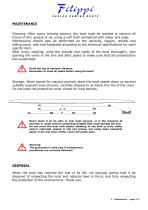
MAINTENANCE Cleaning: After every training session, the boat must be washed to remove all traces of dirt, grease or oil, using a soft cloth dampened with water and soap. Maintenance should also be performed on the oarlocks, riggers, wheels and sliding parts, rails and footplates according to the technical specifications for each specific item. After every washing, rinse the outside and inside of the boat thoroughly, also opening the vents in the fore and after peaks to make sure that all condensation has evaporated. Avoid the use of abrasive cleaners. Remember to close all peaks before using...
Open the catalog to page 4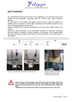
BOAT TRANSPORT For transporting the boat by hand, the suggestion is to lift the boat at the height of the gunwales, ensuring that all carriers have been properly trained. For transport on the trailer, the riggers must first be removed, wrapped in bubble wrap or placed in their bags (optional) and loaded properly so as not to be damaged during the trip. Close all hatches fore and aft bulkheads and secure the sliding seats with straps. Place the boat gunwales on an adequate number of supports, ensuring that the boat is resting on them properly (if required, use shaped foam supports at least as...
Open the catalog to page 5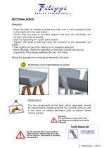
SECTIONAL BOATS Assembly: - Place the boat on trestles making sure that hull is well-supported close to the sections to be assembled. - Check that the boat is correctly aligned and that the bulkheads are facing in the right directions. - Start by tightening the upper bolts loosely. - Tighten the bolts of the keel until the surfaces of the bulkheads are sealed. - Then tighten all the bolts moving in a crosswise direction. - When finished, check the tightness of the bolts without leaving any imperfectly fitted areas between the two half-shells. Follow the procedure in reverse to dismantle the boat....
Open the catalog to page 6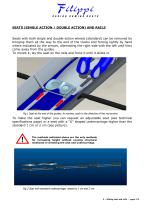
SEATS (SINGLE ACTION / DOUBLE ACTION) AND RAILS Seats with both single and double-action wheels (standard) can be removed by bringing them all the way to the end of the tracks and forcing lightly by hand where indicated by the arrows, alternating the right side with the left until they come away from the guides. To mount it, lay the seat on the rails and force it until it slides in. Fig.1 Seat at the end of the guides: to remove, push in the direction of the red arrows. To make the seat higher you can request an adjustable seat (see technical specifications page) or a seat with a “U” shaped undercarriage...
Open the catalog to page 7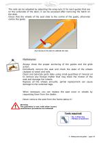
The rails can be adjusted by adjusting the wing nuts (2 for each guide) that are on the underside of the deck; it can be accessed after removing the hatch on the deck. Check that the wheels of the seat slide to the centre of the guide, otherwise centre the guide. Fig.3 Access to the deck to calibrate the rails. Maintenance: Always check the proper anchoring of the guides and the glide action. Periodically remove the seat and check the state of the wheels (subject to wear) and rails. Clean and lubricate parts daily using small quantities of mineral oil to remove any foreign matter that may block...
Open the catalog to page 8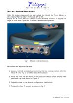
SEAT WITH ADJUSTABLE HEIGHT With this chassis (optional) you can adjust the height (to 7mm, 14mm or 21mm) and the inclination of the seat (0° to 5°). Figure No. 1 shows the new chassis in the standard position, ie height and angle at zero while Figure No. 3 shows a possible configuration. Fig. 1 – Chassis in standard position. Instructions for adjusting the seat 1. Loosen, without completely unscrewing, the two screws marked with the letter 'A' (See fig. 1) on either side of the chassis 2. Move the seat and the frame in the direction of the yellow arrows until you reach the limit shown in Figure...
Open the catalog to page 9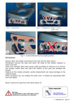
Fig. 3 – Configuration: Height +14 mm. Angle 5 deg. Fig. 4 – Correct (left) and incorrect (right) positions. Maintenance: Always check the proper anchoring of the rails and the slide action. Periodically remove the seat and check the state of the wheels (subject to wear) and rails. Clean and lubricate parts daily using small quantities of mineral oil to remove any foreign matter that may block the motion of the seat and damage the wheels. Replace all the wheels annually: partial replacement can cause damage to the undercarriage. When necessary you can replace the seat cover or wheels by requesting...
Open the catalog to page 10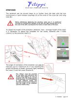
STRETCHER The stretcher can be moved closer to or further from the seat with the two nuts/screws or quick-release couplings (A) at the ends of the cross bar and wing nuts (B). Before definitively tightening the stretcher make sure it is positioned correctly by checking the equality of the left and right moving parts or in the case of the skiff, counting the free holes on both sides of the boat. To adjust the height of the stretcher (distance: heel - average height of the seat) it is necessary to adjust the footplate for the shoes, fastened with 3 bolts (10mm) to the stretcher itself (C). The...
Open the catalog to page 11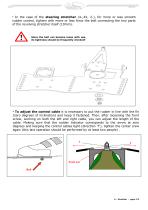
In the case of the steering stretcher (4-,4X, 2-), for more or less smooth rudder control, tighten with more or less force the bolt connecting the two parts of the revolving stretcher itself (10mm). ● Since the bolt can become loose with use, its tightness should be frequently checked! To adjust the control cable it is necessary to put the rudder in line with the fin (zero degrees of inclination) and keep it fastened. Then, after loosening the front screw, working on both the left and right cable, you can adjust the length of the cable. Making sure that the rudder indicator corresponds to the...
Open the catalog to page 12All Filippi catalogs and brochures
 FILIPPI MOULDS
1 Page
 Filippi catalog 2019
36 Pages
 Filippi_Boats_Calendar_2018
38 Pages
 RACING ROWING BOATS
27 Pages
 The blade pitching
24 Pages
 The stroke
30 Pages
 the oars
24 Pages